Video compression system

a compression system and video technology, applied in the field of video compression system, can solve the problem that the 2-dimensional inverse transformation function typically takes a large portion of the time to decode a fram

Inactive Publication Date: 2006-04-11
GOOGLE LLC
View PDF6 Cites 107 Cited by
  • Summary
  • Abstract
  • Description
  • Claims
  • Application Information

AI Technical Summary

Benefits of technology

[0030]Additional savings are achieved by an embodiment of this technique whereby the same coefficient for every block in the image is encoded in the bit-stream before moving on to the next coefficient. In this way, one look up can be performed for each coefficient in the transform to determine where to place the transform coefficient.

Problems solved by technology

The 2-dimensional inverse transform functions typically take a large portion of the time to decode a frame due to their complexity.

Method used


Image

  • Video compression system
  • Video compression system
  • Video compression system

Examples


Embodiment Construction

[0035]The invention includes enhanced video processing and compression and is further described hereinafter.

[0036]The encoder uses a motion estimator, block based 8×8 Discrete Cosine Transform (DCT), a quantizer, a variable length encoder, and a loop filter for smoothing block edges in the reconstruction buffer. The decoder uses a variable length decoder and inverse quantizer, a motion compensator and a loop filter for smoothing block edges.

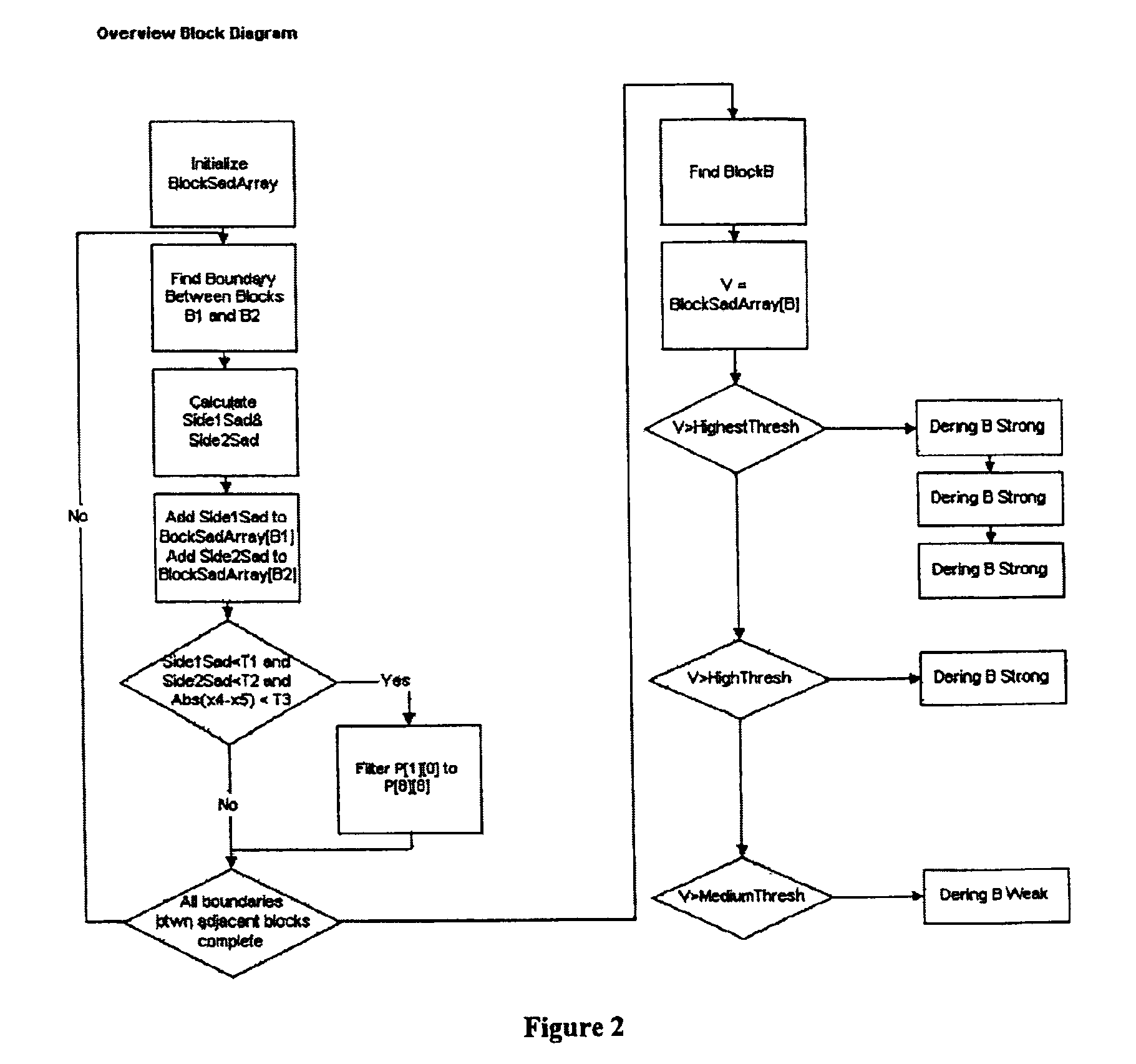
[0037]Two separate image artifacts are produced as a result of the quantization step. A blocking artifact is produced when quantization of the DCT coefficients in adjacent blocks produces pixel values on the shared block edge that differ on either side of the edge by a greater amount than in the original image. A ringing or mosquito artifact results from the quantization of higher frequency components of the transform around strong edges in the image. This means that the transform basis vectors do not reinforce and cancel correctly, producing edg...


PUM


Abstract

An improved video compression system in which the coefficient transform is sped up via folding transposition of coefficients into the token extraction phase. This is accomplished by filling a group of blocks coefficient buffers with 0's before the start of coefficient decoding, extracting the token from the bitstream and placing any extracted coefficient value which is non zero into the transposed order that best suits the target processor.

Description

RELATED APPLICATIONS[0001]This nonprovisional application claims domestic priority to prior provisional application Ser. No. 60 / 312,941, filed Aug. 16, 2001, and to provisional application Ser. No. 60 / 316,316, filed Aug. 31, 2001. Both provisional applications are incorporated herein by reference.PRIOR ART[0002]U.S. Pat. Nos. 6,178,205; 6,167,164; and 6,188,799 entitled “AN EFFICIENT REAL TIME ALGORITHM TO SIMULTANEOUSLY REDUCE BLOCKING AND RINGING ARTIFACTS OF COMPRESSED VIDEO” by Min-Cheol Hong, Chang Mo Yon and Young Man Park, assigned to Digital Media Research Lab IEEE 1999.COMPUTER PROGRAM LISTING APPENDIX[0003]The following computer software files, submitted herewith on one (1) CD-R compact disc, are incorporated by reference herein:[0004]Format:IBM CompatibleOS:WindowsDirectory of CD08 / 06 / 0201:53 p12,710blockmap.c08 / 06 / 0201:53 p8,616blockmapping.c08 / 06 / 0201:53 p1,884blockmapping.h08 / 06 / 0201:53 p5,590borders.c08 / 06 / 0201:53 p4,796cbitman.c08 / 06 / 0201:53 p1,660cbitman.h08 / 06 / 0201...

Claims


Application Information

Patent Timeline
Patent Type & Authority Patents(United States)
IPC IPC(8): G06K9/40
CPCH04N19/86
Inventor AMERES, ERIC L.BANKOSKI, JAMES B.XU, YAOWULA VARNWAY, SCOTT J.GRANGE, ADRIAN W.WILKINS, PAUL G.
Owner GOOGLE LLC
Why Eureka
Try Eureka