Digital electronic volume/flow control sensor toilet

a digital electronic and sensor toilet technology, applied in the field of toilets, can solve the problems of increasing water bills for consumers, deteriorating rubber seals around flapper valves, and leakage typically occurring

Inactive Publication Date: 2006-04-18
SANDERSON DILWORTH D
View PDF53 Cites 53 Cited by
  • Summary
  • Abstract
  • Description
  • Claims
  • Application Information

AI Technical Summary

Benefits of technology

[0016]An additional HOLD button / switch can also be mounted on the outer surface of the water storage tank. The HOLD button / switch, when activated by a user in combination with one of the VOLUME SELECTION buttons / switches, causes water to fill the container to the volume associated with the selected VOLUME SELECTION button / switch. Electrical leads are interconnected to the contact points and are sealed within the volume sensor. These electrical leads pass through and emerge from the top of the volume sensor. The volume sensor passes through the shuttle. As an alternative to the volume selection button / switch and hold button / switch, a load sensor can be interconnected with the volume sensor to automatically sense a load and cause water to fill the container of the flushing mechanism to the volume associated with the amount of load sensed by the load sensor.
[0018]The plunger assembly is an elongated rod with a top end and a bottom end. The rod is preferably made of durable material, such as metal, plastic, or the like. A water sealing plunger element is attached to the bottom end of the rod. The water sealing plunger element is preferably made of flexible water resistant material, such as rubber or the like. A straight gear ratchet is attached to the top end of the rod and is configured to interact with a gear on the motor. The plunger assembly moves up and down and causes the plunger element to open and close the circular aperture at the lower end of the container. When the plunger element is open the container release any water contained therein, and when the plunger element is closed the container can be filled with water.

Problems solved by technology

Leaks typically occur when the rubber seal around the flapper valve deteriorates due to aging and corrosion.
The resulting leak, which may go undetected for a long period of time, causes water to drain slowly into the toilet bowl, leading to increased water bills for consumers.
Leaks also occur because the force from the rising float may not be enough to engage the water-stop valve.
This situation, which also may go undetected for a long period of time, happens when the float is aged and the pivot mechanism develops fractures due to deposits.
If the water-stop valve is not activated, the water in the water storage tank will leak through the stand-up tube into the toilet.
Leaks also occur when the water storage tank is damaged.
This situation is easily detected easily since the floor around the toilet becomes wet.
Leaks also occur when the water-stop valve malfunctions.
In this situation, water continues leaking into the water storage tank until the water-stop valve is replaced.
If a leak remains undetected for a long period of time, a substantial amount of water can be wasted and extensive water damage may occur.
This situation can be even worse in hotels or motels, where some toilets are not frequently used.
If a leak exists in any component, water leaks out of the tank but no water is allowed to flow into the water storage tank.
Although this modification is technically feasible, proper installation of the latch attachment is almost impossible.
In particular, when the water level in the water storage tank changes due to a leak, the pendulum is not able to keep the valve in the shut-off position.
Furthermore, the latch attachment cannot be applied to other flush systems.
The tank ballcock modification cannot be applied to other flush systems.
If it is too short, it won't be able to open the pin valve, and if it is too long, it generates a reaction force that eventually damages both the pin valve and the mounting area of the activating pin.
Designing a mechanism to control this stroke increases the manufacturing cost and requires adjustments during and after installation.
A larger stand-up tube may not fit well in a variety of flush systems.
Furthermore, the pivot mechanism may become clogged after long periods of use, and because of the weight of the dual-valve modification, the user may feel a heavier resistance than with a regular flush system.

Method used


Image

  • Digital electronic volume/flow control sensor toilet
  • Digital electronic volume/flow control sensor toilet
  • Digital electronic volume/flow control sensor toilet

Examples


Embodiment Construction

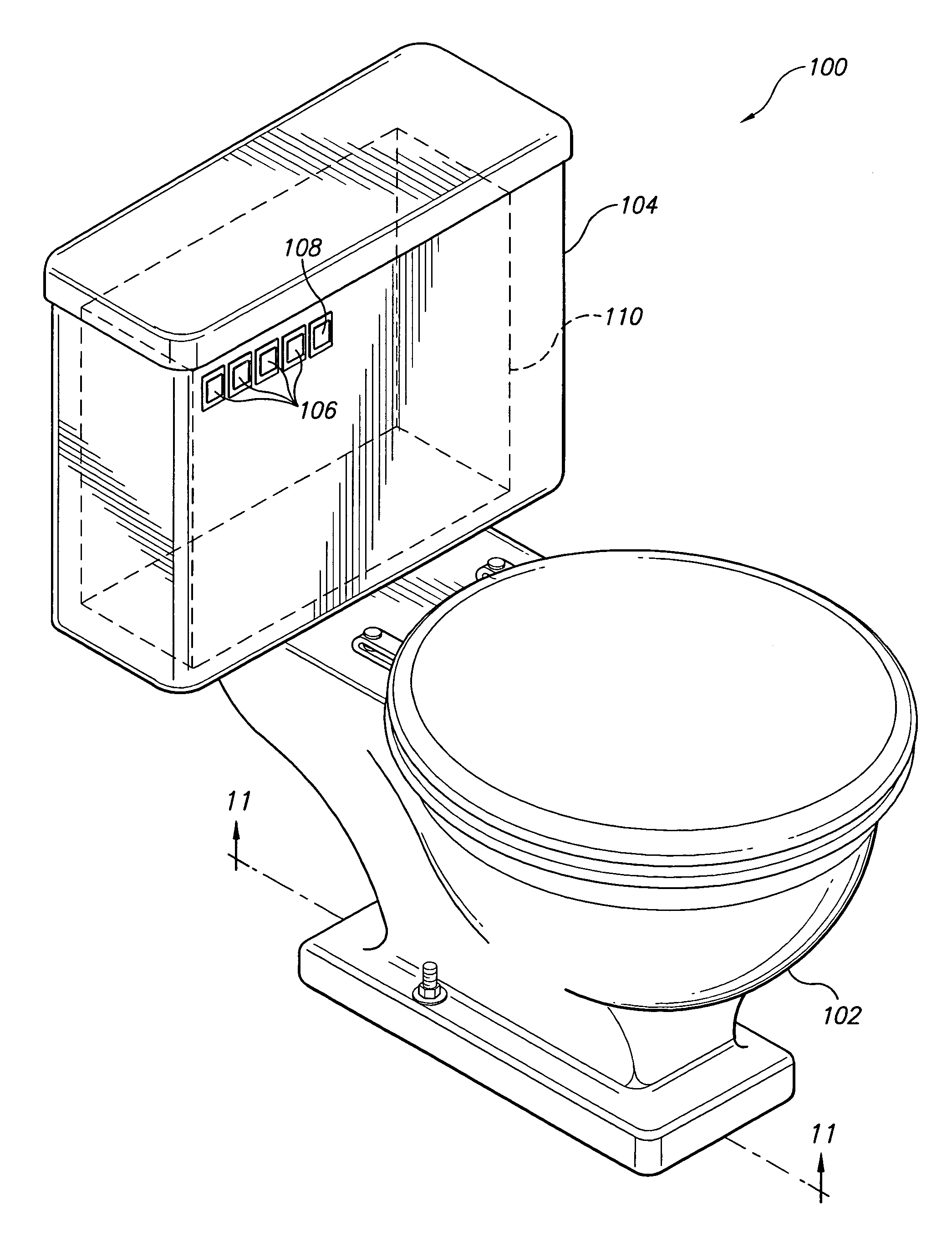
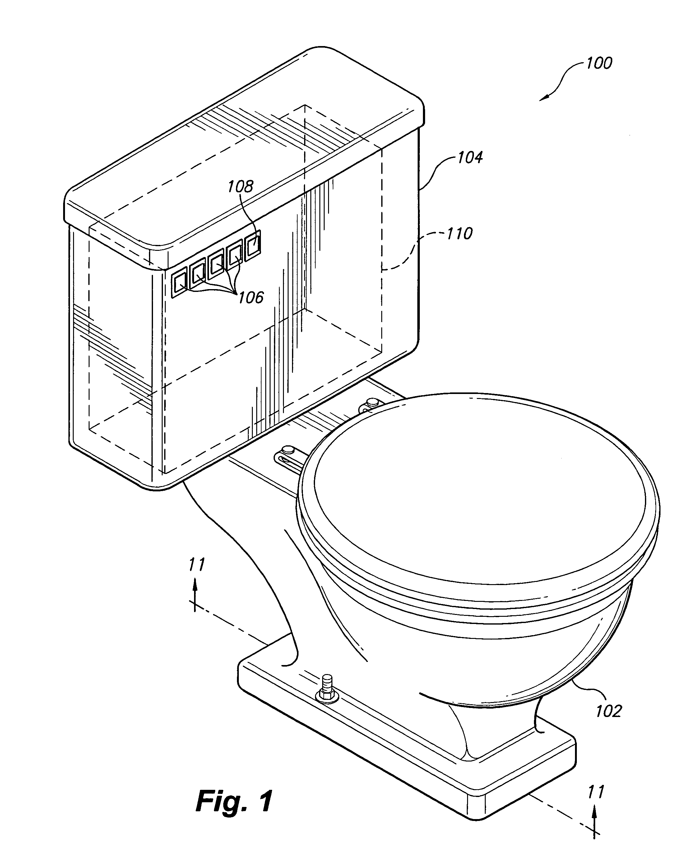
[0035]The present invention is a digital electronic volume / flow control sensor toilet. The invention disclosed herein is, of course, susceptible of embodiment in many different forms. Shown in the drawings and described herein below in detail are preferred embodiments of the invention. It is to be understood, however, that the present disclosure is an exemplification of the principles of the invention and does not limit the invention to the illustrated embodiments.

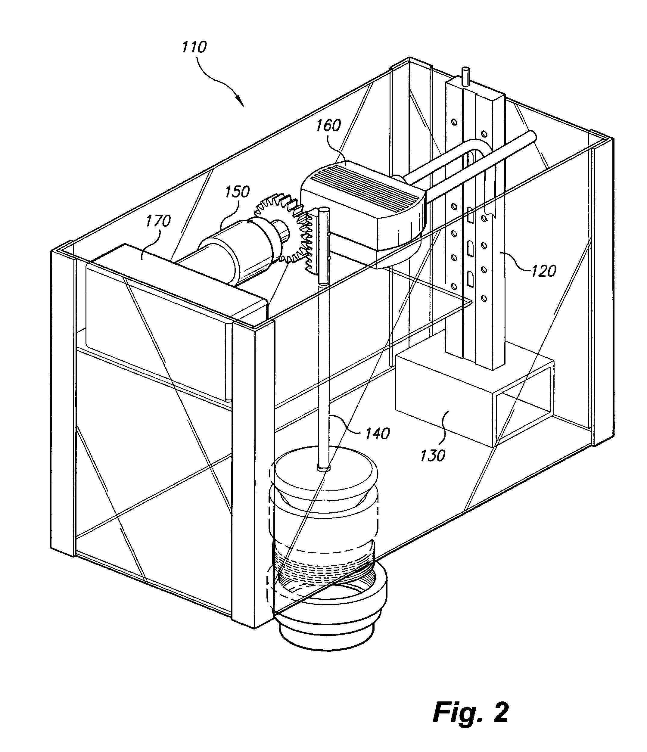
[0036]Referring to the drawings, FIGS. 1–11 show various digital electronic volume / flow control sensor components of a digital electronic volume / flow control sensor toilet 100 according to the present invention. It is the full intent of the inventor that the digital electronic volume / flow control sensor components described herein may either be fully integrated in a newly manufactured toilet or utilized to retrofit an existing toilet. The components themselves may be provided to users as a kit for retrofitting an existing ...


PUM


Abstract

A digital electronic volume / flow control sensor toilet includes a bowl, a water storage tank interconnected with the bowl, and a digital electronic volume / flow control sensor flushing mechanism. The flushing mechanism has components including a volume sensor, a shuttle, a plunger assembly, a motor, a water valve, and a control with a power source and volume / flow control sensor circuitry communicatively interconnecting the components. The volume sensor has a plurality of electrically conductive contact points exposed on a surface and at positions along a length of the side of the volume sensor with a recess, the positions of the contact points corresponding to predetermined volume levels of the flushing mechanism. A plurality of VOLUME SELECTION buttons / switches are mounted on an outer surface of the water storage tank, the VOLUME SELECTION buttons / switches being associated with the contact points. A HOLD button / switch can be mounted on the outer surface of the water storage tank.

Description

CROSS-REFERENCE TO RELATED APPLICATION[0001]This application claims the benefit of U.S. Provisional Patent Application Ser. No. 60 / 606,368, filed Sep. 1, 2004, which is incorporated herein by reference.BACKGROUND OF THE INVENTION[0002]1. Field of the Invention[0003]The present invention relates generally to toilets and, more particularly, to a digital electronic volume / flow control sensor toilet.[0004]2. Description of the Related Art[0005]Toilets are well known and all involve flushing mechanisms to pass waste down a drain. Toilets typically include a bowl through which water passes to receive and remove matter, and a water storage tank interconnected with the bowl to replenish water after the flushing has emptied the bowl. Typical flushing mechanisms include a flush handle interconnected with a float, a flapper valve, and a water-stop valve. When the flush handle is pressed, the flapper valve opens and releases water from the water storage tank into the toilet. The float drops and...

Claims


Application Information

Patent Timeline
Patent Type & Authority Patents(United States)
IPC IPC(8): E03D1/14
CPCE03D1/00E03D5/10Y10S4/03E03D1/18
Inventor SANDERSON, DILWORTH D.
Owner SANDERSON DILWORTH D
Why Eureka
Try Eureka