Method of making a miniaturized positional assembly

a positional assembly and miniaturization technology, applied in the direction of instruments, magnetic bodies, diagnostic recording/measuring, etc., can solve the problems of many problems, difficult to maintain the mutually orthogonal orientation of the inductive coil during its lifetime, and difficult to manufacture the unit in which the coils resid

Inactive Publication Date: 2006-04-18
ADVANCED NEUROMODULATION SYST INC
View PDF16 Cites 74 Cited by
  • Summary
  • Abstract
  • Description
  • Claims
  • Application Information

AI Technical Summary

Problems solved by technology

Heretofore, the manufacture of the unit in which the coils reside has been a challenging and expensive operation.
Performing this method resulted in many problems.
First, there was the difficulty in maintaining the mutually orthogonal orientation of the inductive coils during their insertion into the tube and the filling of the tube with epoxy.
Another difficulty in the manufacture of a device bearing orthogonally oriented inductive coils is the achievement of true orthogonal orientations.
At the fraction of a millimeter scales required to create a device that can be moved through small blood vessels, it is not easy to ensure that each inductive coil is placed within 89.9° and 90.1° of the orientation of the others.

Method used


Image

  • Method of making a miniaturized positional assembly
  • Method of making a miniaturized positional assembly

Examples


Embodiment Construction

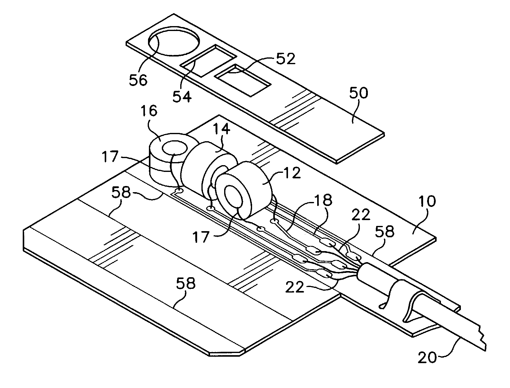
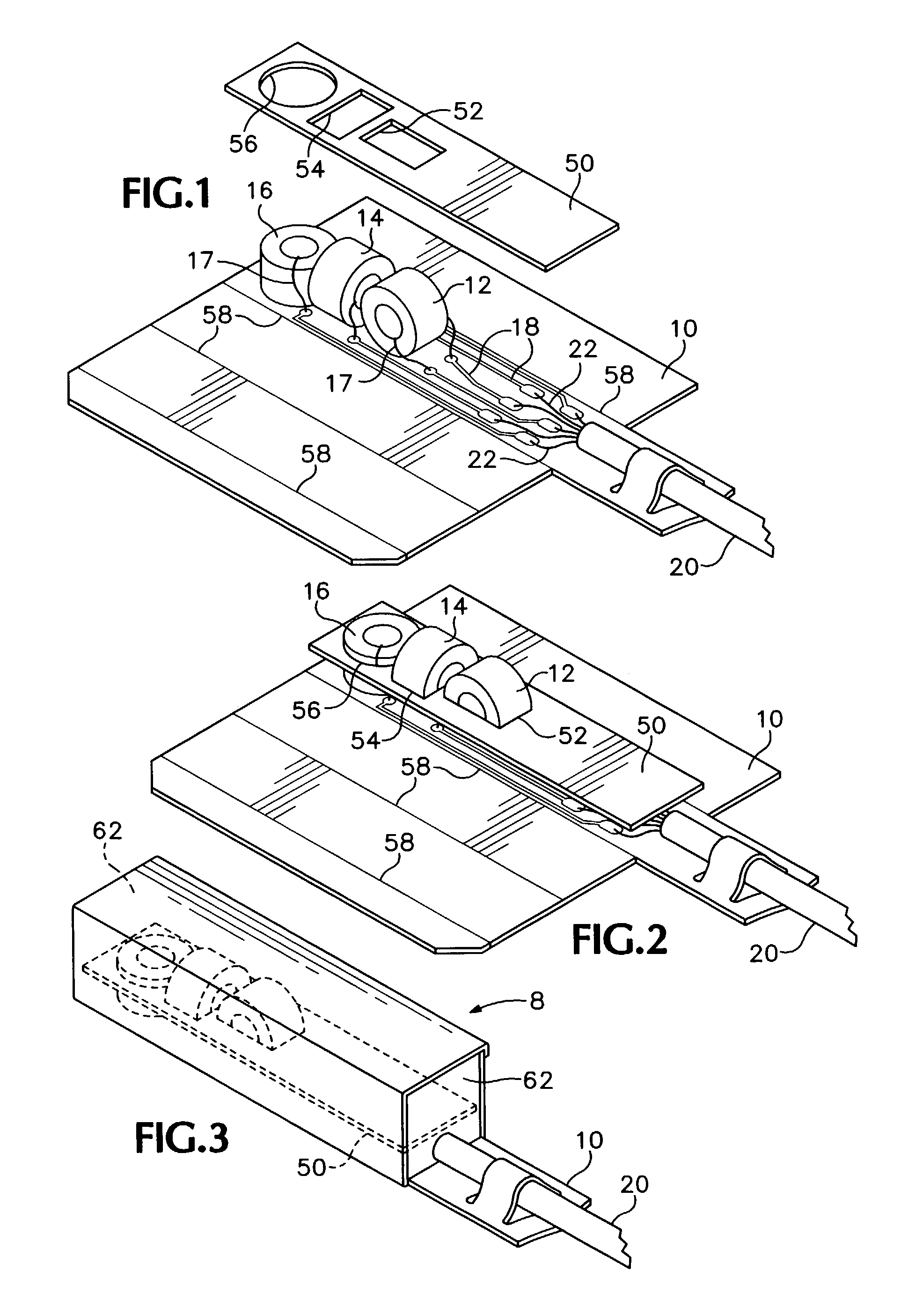
[0011]Referring to FIGS. 1–3, in a first preferred embodiment of a method of manufacturing a miniaturized positional assembly 8 (FIG. 3), a piece of flex-circuit 10 is provided that is sized to accommodate a set of inductive coils 12, 14 and 16 when folded into a square tube. The flex circuit has a set of six traces 18, each of which extends from an area adapted to connect to a set of wires 22, to a position adapted to permit the attachment of a terminal 17 of one of the inductive coils 12, 14 and 16. In an alternative preferred embodiment the terminal wires of coils 12, 14 and 16 are extended to attach directly to the ends of wires 22, which are far greater in diameter.

[0012]Each of the three coils 12, 14 and 16 may be placed by a robot onto the flex circuit, which preferably has been readied for each with a drop of epoxy to hold the coil in place during further operations. The termini (not shown) of each coil are then soldered to the appropriate flex circuit trace 18. A cable 20 i...


PUM

PropertyMeasurementUnit
diameteraaaaaaaaaa
lengthaaaaaaaaaa
diameteraaaaaaaaaa

Abstract

A method of producing a miniaturized set of inductive coils set mutually orthogonally inside a tube. In the method a positional template made of a sheet of substantially rigid material that defines a set of guide apertures, each of which is in the shape of one of the set of inductive coils. The guide apertures are disposed so that when an inductive coil is fitted into each one of the guide apertures the coils will be substantially orthogonal to one another.

Description

BACKGROUND OF THE INVENTION[0001]The ability to accurately determine the position of a device within the body currently yields a considerable benefit for at least one medical procedure. This is the electrophysiological mapping of the heart. Such mapping frequently permits the location and treatment of the neurological disorder that has given rise to a heart arrhythmia. In order to accurately perform this mapping a transceiver head must be introduced into the heart by way (in part) of the femoral artery. The position and orientation of this transceiver head must be accurately monitored.[0002]In order to perform this monitoring a set of orthogonally positioned inductive coils are fixed at the transceiver head and conductively connected through the catheter to the outside of the body, where the current in each of the inductive coils can be read. Cooperating with these coils, powerful magnets are arrayed about the imaging station, so that the current through each coil is dependent on it...

Claims


Application Information

Patent Timeline
Patent Type & Authority Patents(United States)
IPC IPC(8): H01F7/06B65H18/28H01F5/00
CPCA61B5/06G01D5/2086G01D11/245H01F5/00A61B5/042Y10T29/49073H01F27/306Y10T29/49071Y10T29/49087Y10T29/4902H01F27/02A61B5/062A61B5/283
Inventor HUYNH, KYBOOGAARD, JEROME J.
Owner ADVANCED NEUROMODULATION SYST INC
Why Eureka
Try Eureka