Method for computation of differential azimuth from spaced-apart gravity component measurements

a gravity component and gravity computation technology, applied in the field of method for computing differential azimuth from spacedapart gravity component measurements, can solve the problems of not consistently obtainable acceptable results for all possible input conditions, and demonstrating less geometrical accuracy than the preferred method

Inactive Publication Date: 2006-04-18
SCIENCE DRILLING INTERNATIONAL INC
View PDF15 Cites 27 Cited by
  • Summary
  • Abstract
  • Description
  • Claims
  • Application Information

AI Technical Summary

Problems solved by technology

No details are there provided on the development of the equation shown therein for differential azimuth and there are issues with that equation that lead to a conclusion that acceptable results are not consistently obtainable for all possible input conditions.
Further, it is an objective to provide two alternative embodiments that are simpler computationally, but demonstrate less geometrical accuracy than the preferred method.

Method used


Image

  • Method for computation of differential azimuth from spaced-apart gravity component measurements
  • Method for computation of differential azimuth from spaced-apart gravity component measurements
  • Method for computation of differential azimuth from spaced-apart gravity component measurements

Examples


embodiment

PREFEREED EMBODIMENT

[0042]Since the method of this invention determines only changes in the azimuth orientation of a borehole between two spaced-apart locations along the borehole, the initial azimuth angle may be considered as zero. This simplifies the equations below without any loss in the general usefulness of the method.

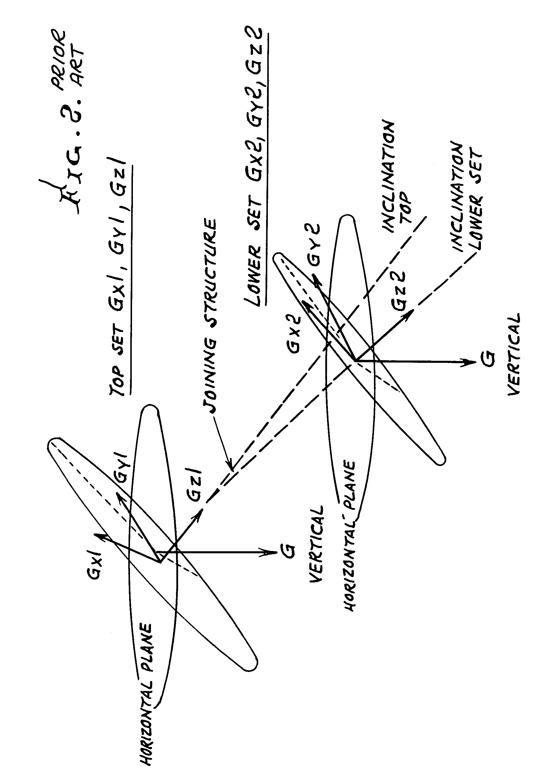
[0043]Given an X,Y,Z earth fixed coordinate set having X horizontal at any arbitrary, assumed zero, azimuth angle with respect to north, Y horizontal and normal to X and Z down and given an x1,y1,z1 borehole fixed coordinate set for a first set of gravity component measurement devices related to X,Y,Z by rotations:

[0044]Alpha, α, about Y which is a tilt or inclination angle

[0045]Beta, β, about the new Z′ axis which is a gravity highside angle

The x1,y1,z1 coordinate set is related to the X,Y,Z coordinate set by the direction cosine matrix C1 whose elements are:

C1(x1,X)=Cos(α)Cos(β)

C1(x1,Y)=Sin(β)

C1(x1,Z)=−Sin(α)Cos(β)

C1(y1,X)=−Cos(α)Sin(β)

C1(y1,Y)=Cos(β)

C1(y1,Z)=...

first alternative embodiment

[0050]Given an X,Y,Z earth fixed coordinate set having X at any arbitrary angle with respect to north, Y normal to X and Z down and given an x,y,z borehole fixed coordinate set for a first set of gravity component measurement devices related to X,Y,Z by rotations:[0051]Alpha, α, about Y which is a tilt angle[0052]Beta, β, about the new Z′ axis which is a highside angle

And given another x,y,z borehole fixed coordinate set for a second set of gravity component measurement devices related to the prior x,y,z borehole fixed set by rotations:[0053]Gamma, γ about the new Y″ axis which is a bend angle of the drill string[0054]Delta, δ, about the new X′″ axis which is a bend angle of the drill string orthogonal to gamma

This last x,y,z coordinate set is related to the X,Y,Z coordinate set by a nine-element direction cosine matrix. The elements of that matrix are:

C(x,X)=−Sin(α)Sin(γ)+Cos(α)Cos(β)Cos(γ)

C(x,Y)=Sin(β)Cos(γ)

C(x,Z)=−(Cos(α)Sin(γ)+Sin(α)Cos(β)Cos(γ))

C(y,X)=Sin(δ)(Sin(α)Cos(γ)+Cos(α)...

second alternative embodiment

[0055]An approximate solution to the problem described above is found from U.S. Pat. No. 4,071,959, Gyro Stabilized Single-Axis Platform, at Column 3, Line 5, to Column 5, Line 51. This patent provides the basis for the Sperry Sun B.O.S.S. survey tool. That tool has a single set of accelerometers mounted on a gyro stabilized single axis platform having its stabilization axis along the borehole. As the tool travels along the borehole, it follows the bends of the borehole but is, in effect, torsionally rigid about the borehole axis. Thus subsequent sets of accelerometer measurements are equivalent to the mode described above. This solution is based on the small-angle assumption for which the sine of the angle is the angle and the cosine of the angle is one.

Equation E of the patent shows the solution as:

ΔΨ=−(1 / Cos Θ))ΔΦ2

[0056]where ΔΨ is the change in azimuth between the two sets of data

Θ is the inclination angle ΔΦ2 is the change in high side angle between the two sets of data

Placed i...


PUM


Abstract

A method is provided for computing the differential azimuth between two sets of spaced-apart gravity component measurement devices in a borehole, employing multiple rotation angles. The method includes modeling relationships of axes as defined; forming equations relating rotation angles to outputs of gravity measuring devices; solving such equations to derive the values representative of all of the rotation angles, using measured values of the outputs from the first and second sets of gravity component measuring devices, and computing from the values of the rotation angles the differential azimuth angle between the first set and the second set of gravity measuring devices.

Description

BACKGROUND OF THE INVENTION[0001]This invention relates to the computation of differential azimuth between two sets of spaced-apart gravity component measurement devices in a borehole, subject to the constraint that there is no rotation about the borehole axis between the two sets of measuring devices, generally known as accelerometers. Such a structure cannot determine absolute azimuth orientation but only the differential azimuth between the two spaced-apart sets of gravity component measurements. Such apparatus in general is referenced in prior art U.S. patent application Ser. No. 06 / 200,096, Borehole Survey Apparatus and Method, filed Oct. 23, 1980, describing one such a mechanization. That application was processed to the point of allowance of all claims and then abandoned. Another prior art example is described in U.S. Pat. No. 6,480,119, Surveying a Subterranean Borehole Using Accelerometers, issued Nov. 12, 2002. No details are there provided on the development of the equati...

Claims


Application Information

Patent Timeline
Patent Type & Authority Patents(United States)
IPC IPC(8): G01V1/40E21B47/00E21B47/022G01V7/00G01V7/02G01V7/14G01V7/16
CPCG01V7/16E21B47/022
Inventor ENGEBRETSON, HAROLD J.VAN STEENWYK, BRETT H.
Owner SCIENCE DRILLING INTERNATIONAL INC
Why Eureka
Try Eureka