Hot-gas engine

a technology of hot gas and engine, which is applied in the direction of special engines, ericsson type engines, stirling type engines, etc., can solve the problems of shortening the service life of such components and limiting the achievable thermal efficiency, so as to improve thermal efficiency, simplify the heat supply, and improve the effect of thermal efficiency

Inactive Publication Date: 2006-04-18
SERVIS WILHELM +1
View PDF13 Cites 3 Cited by
  • Summary
  • Abstract
  • Description
  • Claims
  • Application Information

AI Technical Summary

Benefits of technology

[0005]Essentially, the advantages of the invention comprise a simplified heat supply, which is improved in comparison to existing designs, to the working medium contained in the cylinder, and in direct cooling of the working medium in the cylinder, with such direct cooling being obtained by injecting a li

Problems solved by technology

There is a disadvantage in that, in conventional hot-gas engines of the type mentioned, corresponding temperature differences occur also within the cylinder wall and within the walls of the heat-transmitting components, which temperature differences cause serious alternating thermal loads of

Method used


Image

  • Hot-gas engine
  • Hot-gas engine
  • Hot-gas engine

Examples


Embodiment Construction

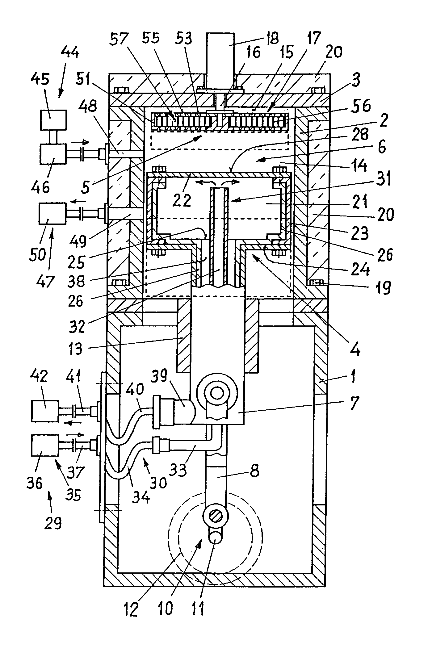
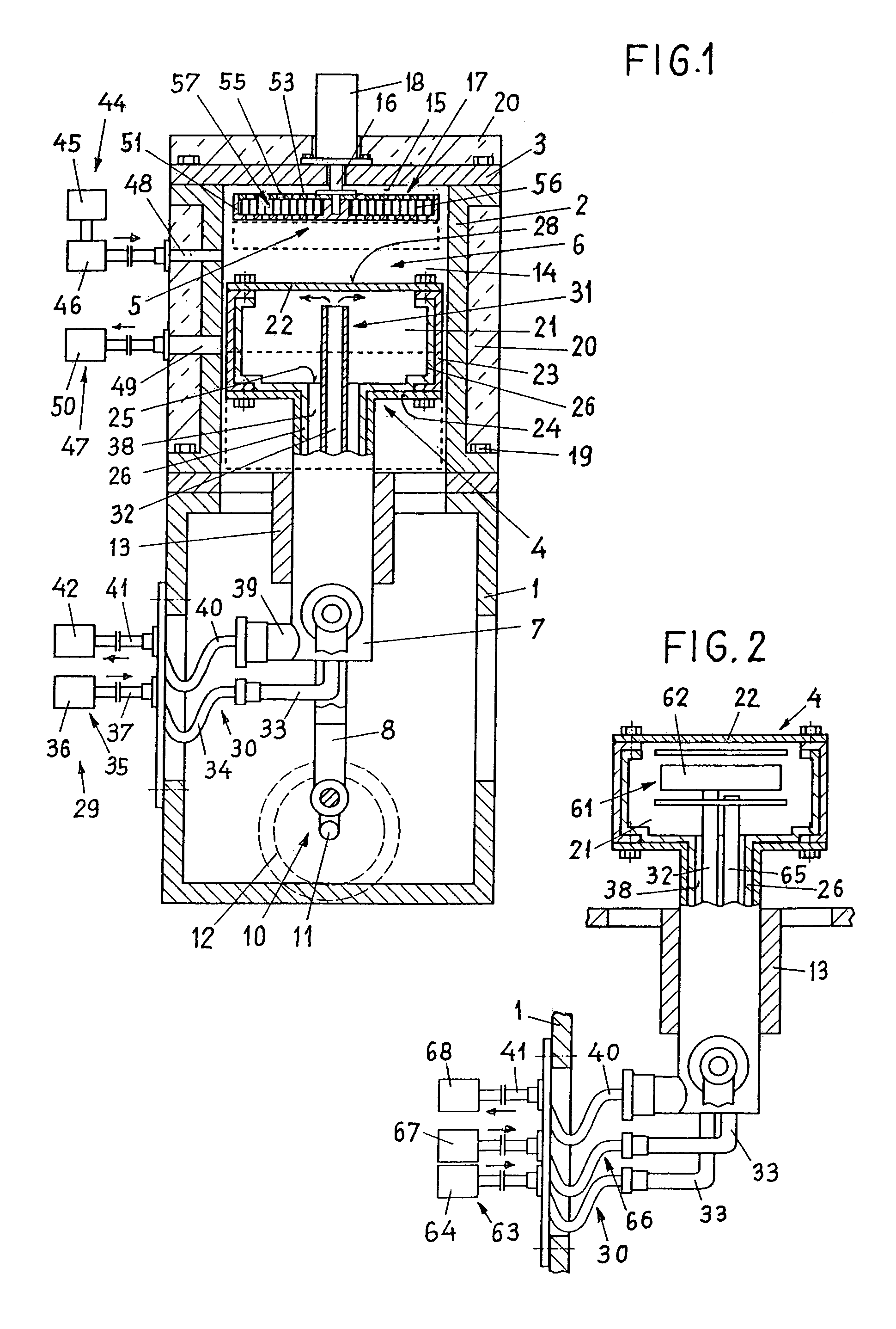
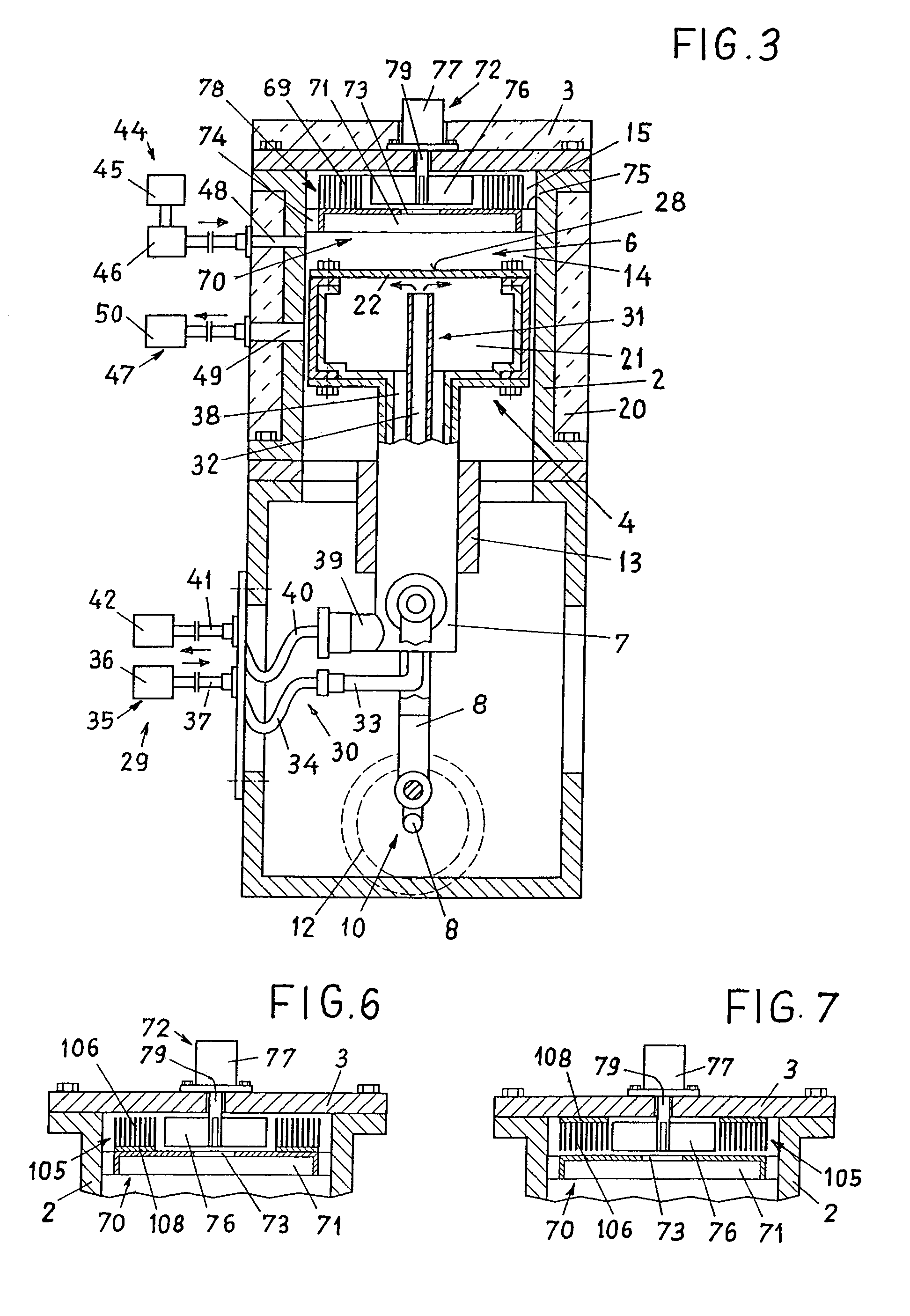
[0015]FIG. 1 shows a Stirling cycle hot-gas engine which comprises a housing 1, a cylinder 2 with a cylinder cover 3, a working piston 4 which is slidably arranged in said cylinder 2, and a displacement device 5 which is arranged between said working piston 4 and the cylinder cover 3. The working piston 4, which together with the cylinder cover 3 delimits a cylinder space 6 which is designed to accommodate any desired working medium e.g. air, helium or the like, can be coupled to a drive arrangement by way of a hollow piston rod 7 and a connecting rod 8 linked to said piston rod 7, with said drive arrangement comprising a crankshaft 11, held in the housing 1, and a flywheel 12. The crankshaft can be coupled to any desired machine, e.g. to a generator (not shown). The piston rod 7 is guided in a crosshead 13 connected to the housing 1 so as to be axially slidable. The cylinder 2 is connected to the housing 1 and to the cylinder cover 3 by means of screws 19. The cylinder 2 and / or the...


PUM


Abstract

The hot-gas engine comprises a cylinder, a working piston which together with a cylinder cover delimits a cylinder space designed to accommodate a working medium, a displacement piston which divides the cylinder space into a first and a second working space, as well as a heating device for heating device for heating up the working medium contained in the first working space, and a cooling device for cooling the heated working medium. The working spaces are connected so as to be communicating by way of a regenerator arranged in the displacement piston. The heating device comprises a heating area on the end wall of the working piston, and a heating arrangement associated with the working piston. The cooling device comprises an injection device for feeding liquefied working medium into the first working space. This design provides improved heat supply to the working medium contained in the cylinder, and further provides direct cooling of said working medium. At the same time, a simpler and compact construction of the hot-gas engine can be achieved.

Description

BACKGROUND OF THE INVENTION[0001]The invention relates to a hot-gas engine.[0002]A hot-gas engine of the type mentioned is known from DE 25 22 711 A1. The known engine, a Stirling cycle engine, comprises a cylinder in which a working piston, which is connected to a crank drive, is arranged so as to move to and fro in relation to a displacement piston, which is connected to the same drive. The displacement piston divides the cylinder space into a first working space, delimited by the cylinder cover, and a second working space, delimited by the working piston. The working spaces are connected to an external connection channel by way of a passage each which is provided in the cylinder wall, with said external connection channel comprising a heating device for heating up the working medium in the first working space, and a cooling device for cooling the working medium in the second working space, as well as a regenerator which is arranged between the heating device and the cooling devic...

Claims


Application Information

Patent Timeline
IPC IPC(8): F01B29/10F02G1/043
CPCF02G1/043F02G2242/00F02G2243/02F02G2243/06F02G2270/85F02G2250/24F02G2254/30F02G2254/90F02G2243/24
Inventor SERVIS, WILHELMVON SEGESSER, LUDWIG K.
Owner SERVIS WILHELM
Why Eureka
Try Eureka