Preventive theft installation on a boat

Inactive Publication Date: 2006-04-18
DE MANGE CRAIG
View PDF5 Cites 0 Cited by
  • Summary
  • Abstract
  • Description
  • Claims
  • Application Information

AI Technical Summary

Benefits of technology

[0002]An object of the invention is to conceal and to prevent the accessibility of some of the bolts that are mounting the drive of the boat to the housing containing the drive shaft of a boat to prevent their removal and thereby the theft of the drive. Of particular interest are the four bolts in the upper section of the drive that are arranged in pairs on each side of the drive.

Problems solved by technology

The remaining 2 bolts are left alone because if the four bolts that are conceale

Method used


Image

  • Preventive theft installation on a boat
  • Preventive theft installation on a boat
  • Preventive theft installation on a boat

Examples


Embodiment Construction

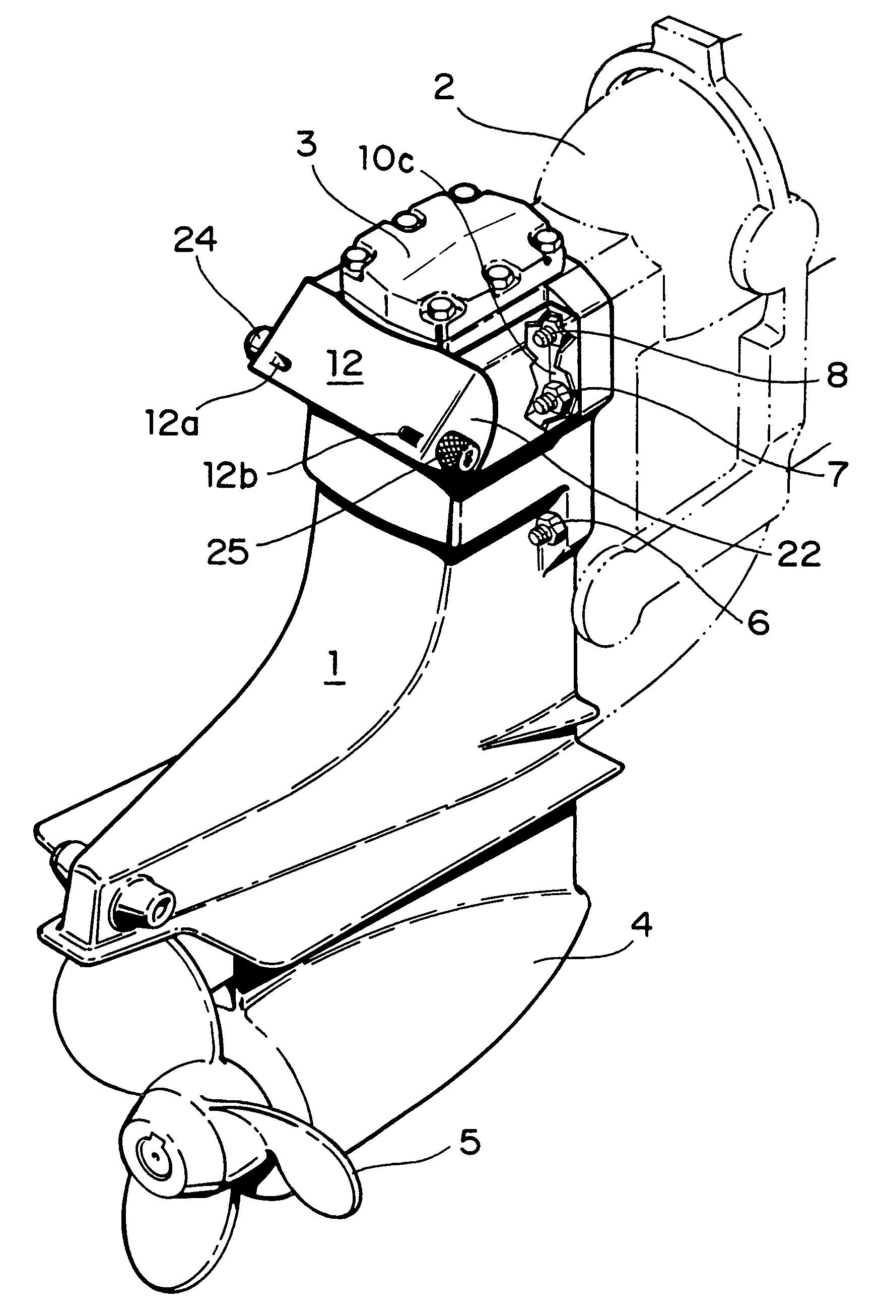
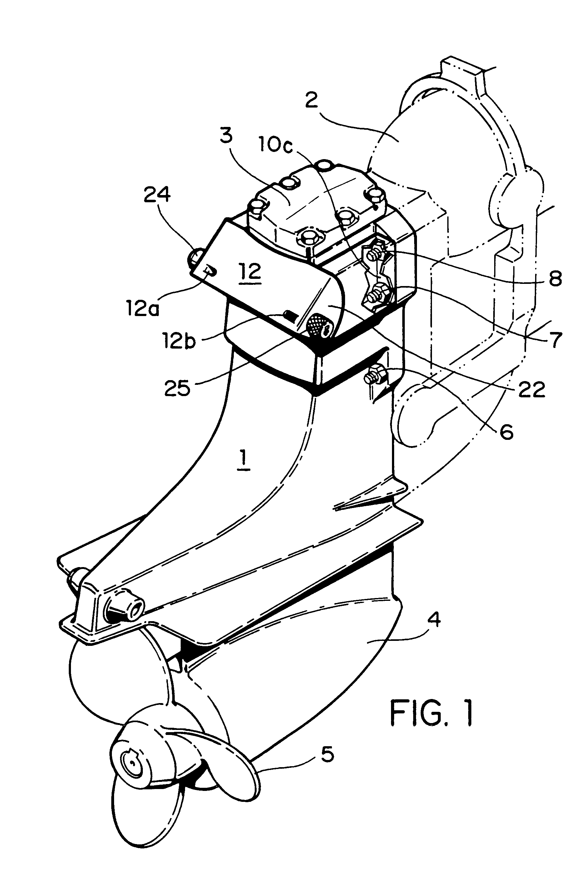
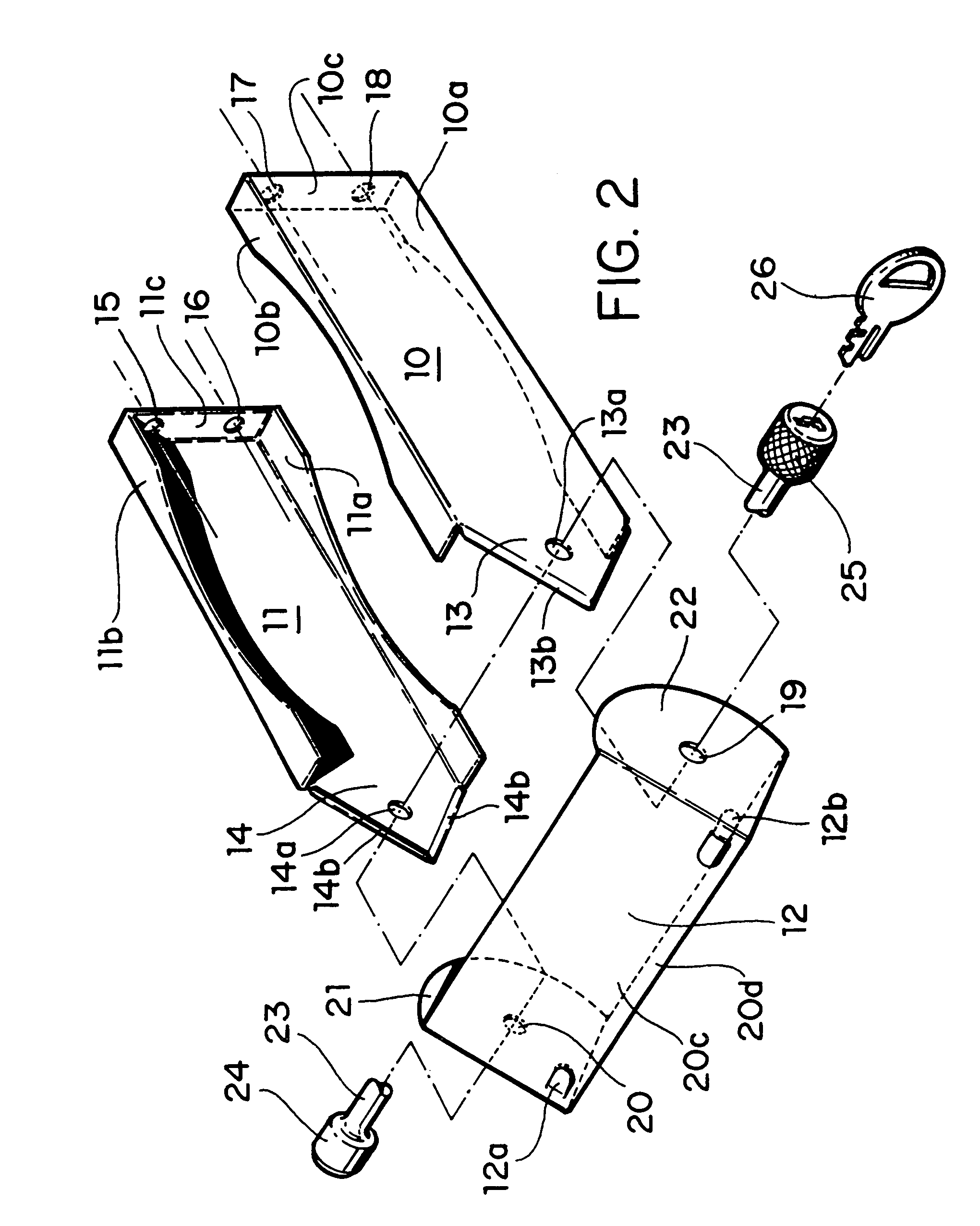
[0005]Turning now to FIG. 1, there is shown a drive 1 for the boat and how it is mounted by bolts 7 an 8 to housing 2 containing the drive shaft from the motor (not shown). The drive itself has an upper section 3 and a lower section 4 operating the propeller 5. Below the upper section 3 there are located two bolts 6 (one on each side) which aid in mounting the drive 1 to the housing 2. The two bolts 7 and 8 with two more bolts (not shown) on the other side of the upper section 3 form a pattern of four bolts with two bolts parallel to each other on each side of the upper section. This pattern of four bolts on the section 3 is obscured from view and, therefore, any tools cannot be attached to these nuts on the bolts to loosen and to remove the same. In FIG. 1, there is shown a broken away flange 10c (FIG. 2) under the nuts 7 and 8 on the upper section of the drive 2. This flange will now be explained with reference to FIG. 2.

[0006]FIG. 2 shows the inventive lock system in an exploded ...


PUM


Abstract

The invention pertains to a theft preventive installation on a boat. Particularly, it is directed to prevent a theft of the drive for the boat at its connection to a housing containing the drive shaft from the motor. It is commonly known that up to six bolts connect the drive to the housing. This particular connection is prone to be broken by unscrewing the bolts whereby the drive can easily be removed from the housing and thereby from the boat. According to the invention, the view of the bolts is obstructed whereby any application of tools to the bolts is prevented. In most installations, there are four bolts placed in a pattern with two bolts each on each side of the upper section of the drive. A plate having inwardly facing flanges thereon is placed under the bolts of each side of the drive. This will securely fasten the plates under the bolts. A third plate having a three-dimensional shape is placed over the ends of the two plates and is spanning the distance between the two plates, A lock bolt passes through the two plates and parts of the third plate. This then prevents the bolts from being viewed and any tools from being applied to the bolts or nuts on the bolts.

Description

BACKGROUND OF THE INVENTION[0001]The present invention pertains to a theft prevention device on drive installations on a boat. Many drive installations in a boat involve either an outboard motor or in inboard motor. The present device is directed to an inboard installation. In an inboard installation, the motor is mounted within the boat hull in a substantially linear alignment with the boat hull. The motor has a drive shaft extending to the rear of the boat and ends behind the transom of the boat. The drive shaft has a bevel gear which will mesh with the bevel gear of a downward shaft and then to the propeller gear so as to divert the drive of the motor to a different direction that is downwardly and then outwardly below the water line. This gearing is contained in one unit and is known as the drive of the boat and this particular drive is prone to theft because it is mounted behind the transom of the boat on a housing which contains the drive shaft and can easily be removed from t...

Claims


Application Information

Patent Timeline
IPC IPC(8): B63H5/125B63H20/08
CPCE05B73/0076
Inventor DE MANGE, CRAIG
Owner DE MANGE CRAIG
Why Eureka
Try Eureka