Two-dimensional micro-mirror array enhancements

a micro-mirror array and enhancement technology, applied in the field of optical networking devices, can solve the problems of limited scalability and relatively low integration level, and achieve the effects of enhancing instability, reducing the required drive voltage, and increasing electrostatic for

Inactive Publication Date: 2006-04-18
RPX CLEARINGHOUSE
View PDF2 Cites 5 Cited by
  • Summary
  • Abstract
  • Description
  • Claims
  • Application Information

AI Technical Summary

Benefits of technology

[0010]Among the advantages of the present invention are the following. The placement of the electrodes on raised structures on a substrate provides for increased electrostatic force, as well as enhanced instability, thus lowering the required drive voltage and enhancing the deflection angles of the mirrors. The slotted hinge has high torsional flexibility and high stiffness (both vertically and laterally). The dam feature overcomes the undesirable effects of the interaction of the flow of air from adjacent mirrors in a micro-mirror strip assembly.

Problems solved by technology

Prior efforts using this approach, like those of other approaches, tend to have certain shortcomings, such as limited scalability and a relatively low level of integration.

Method used


Image

  • Two-dimensional micro-mirror array enhancements
  • Two-dimensional micro-mirror array enhancements
  • Two-dimensional micro-mirror array enhancements

Examples


Embodiment Construction

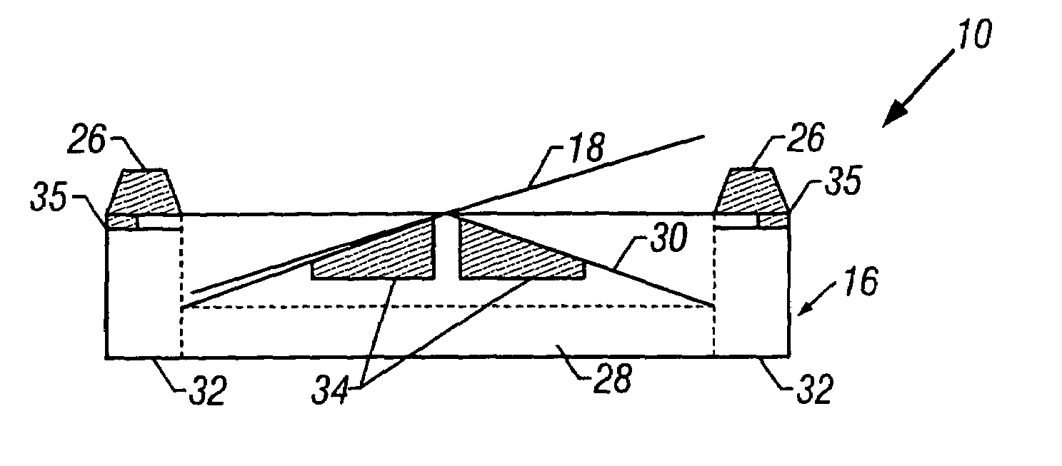
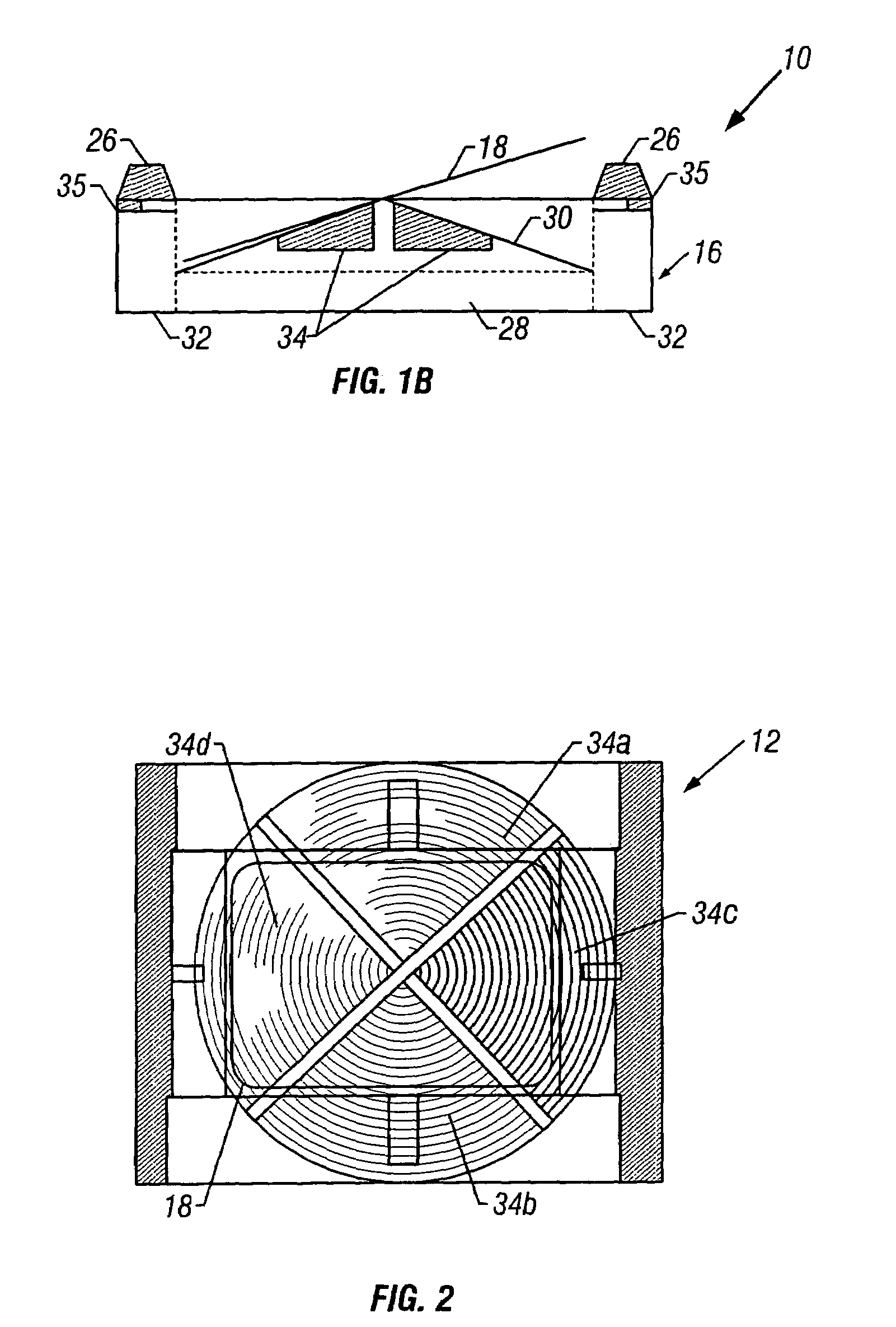
[0043]With reference to FIGS. 1A–1B, a micro-mirror strip assembly 10 includes a plurality of micro-mirror structures 12, each of the micro-mirror structures 12 including a mirror arrangement 14 disposed above and supported over a top surface of a reference member or substrate 16. As shown in FIG. 1A, each mirror arrangement 14 includes a mirror 18 coupled to mirror frame 20 by a first pair of torsion members 22a, 22b. The mirror arrangement 14 further includes a second pair of torsion members 24a, 24b, which couple the mirror frame 20 to strips 26.

[0044]Referring to FIG. 1B, the substrate 16 includes a base portion 28, a raised portion 30 on the base portion 28, and sidewall portions 32 on either side of the base portion 28. The substrate may be made of ceramic or other suitable materials. The strips 26 are located on top of the sidewalls 32. As shown by the raised portion 30 (FIG. 1A), the raised portion 30 is conical or quasi-conical in shape.

[0045]Electrodes 34 are disposed on t...


PUM


Abstract

A micro-mirror strip assembly having a plurality of two-dimensional micro-mirror structures with improved deflection and other characteristics is presented. In the micro-mirror structures, electrodes for electrostatic deflection are disposed on conical or quasi-conical entities that are machined, attached or molded into a substrate. The electrodes are quartered approximately parallel to or offset by 45 degrees from rotational axes to form quadrants. Torsion sensors are provided along the axes of rotation to control deflection of the quadrant deflection electrodes.

Description

CROSS REFERENCE TO RELATED APPLICATIONS[0001]This application claims priority from the following U.S. Provisional Patent Applications, the disclosures of which are incorporated by reference in their entirety for all purposes:[0002]This application is a divisional (and claims the benefit of priority under 35 USC 120) of U.S. application Ser. No. 10 / 157,354, filed May 28, 2002, now U.S. Pat. No. 6,744,550, which is a continuation of U.S. application Ser. No. 09 / 715,945, filed Nov. 16, 2000 now abandoned. The disclosure of the prior application is considered part of (and is incorporated by reference in) the disclosure of this application, and which claims priority to U.S. Provisional Patent Application Ser. No. 60 / 165,863, entitled “Improvements for an Optical N×N Switch,” filed Nov. 16, 1999; U.S. Provisional Patent Application Ser. No. 60 / 168,291, entitled “Scanner Improvements for an Optical N×N Switch,” filed Dec. 1, 1999; U.S. Provisional Patent Application Ser. No. 60 / 183,246, en...

Claims


Application Information

Patent Timeline
Patent Type & Authority Patents(United States)
IPC IPC(8): G02B26/00G02B6/26G02B6/32G02B6/35G02B6/42G02B26/08
CPCG02B6/262G02B6/32G02B6/357G02B26/085G02B26/0833G02B26/0841G02B6/3584G02B6/3512G02B6/356G02B6/359G02B6/4249
Inventor NEUKERMANS, ARMAND P.SLATER, TIMOTHY G.SCHUMAN, MARC R.FOSTER, JACK D.CALMES, SAMBAJIKAR, SATEESH S.MALHOTRA, ARUNANG, JANEHURST, JERRYGREEN, JOHN
Owner RPX CLEARINGHOUSE
Why Eureka
Try Eureka