Timepiece with touch-type reading and control of time data

a timepiece and touch-type technology, applied in the field of wristwatches, can solve the problems of not being able to learn, requiring non-negligent reading, and still having debatable aesthetic appearance of wristwatches corresponding to the aforecited prior ar

Active Publication Date: 2006-04-18
ASULAB SA
View PDF13 Cites 186 Cited by
  • Summary
  • Abstract
  • Description
  • Claims
  • Application Information

AI Technical Summary

Benefits of technology

[0013]This timepiece is characterised in that the bezel includes only four markings at the 3 o'clock, 6 o'clock , 9 o'clock and 12 o'clock time positions and in that the electronic circuit is designed to recognise both a specific manipulation of the crown-push-button (brief or long application of pressure; pulling), activation of an individual sensor, of any sen

Problems solved by technology

Despite these improvements, wristwatches corresponding to the aforecited prior art still have debatable aesthetic a

Method used


Image

  • Timepiece with touch-type reading and control of time data
  • Timepiece with touch-type reading and control of time data
  • Timepiece with touch-type reading and control of time data

Examples


first embodiment

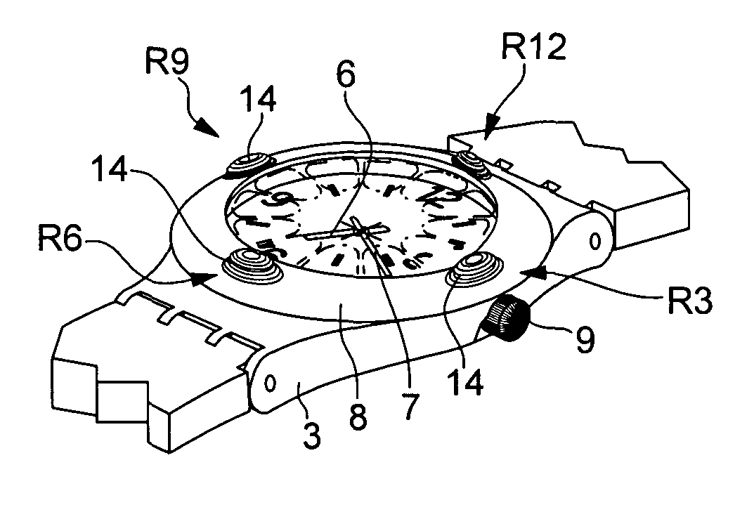
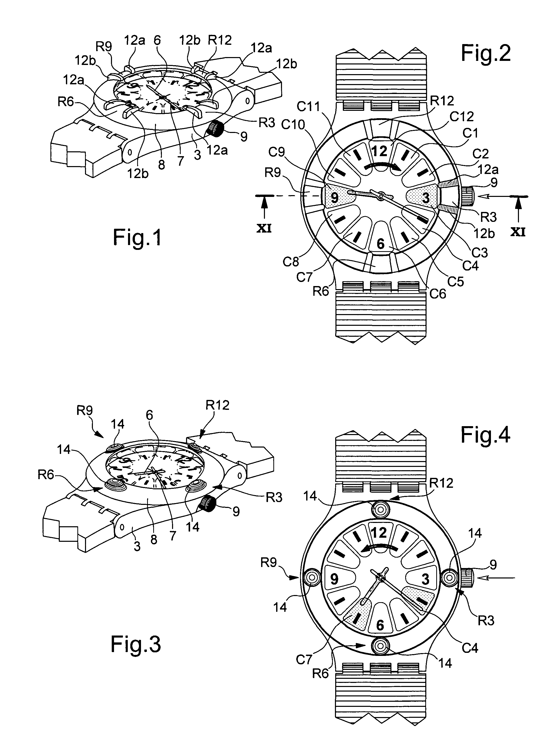
[0024]The position of each sensor, designated generally by Ci, is identified owing to bezel 8 that includes four markings R3, R6, R9 and R12 located at the four time positions 3 o'clock, 6 o'clock, 9 o'clock and 12 o'clock . In this first embodiment, each marking is formed by two bars 12a, 12b in a raised position on the bezel and being spaced at the same distance as the width of the sensor associated with the edge of glass 4. Thus, for example, the user who detects vibrations, with his finger, which he has unknowingly passed over the glass above sensor C3, immediately identifies marking R3 as a result of the two bars 12a, 12b which he feels with his finger on the inner edge of bezel 8, this identification being able to be achieved without any risk of confusion with the bars of the three other markings which are sufficiently far away spatially. The user then knows that his finger was on the 3 o'clock time position. Conversely, if he wishes to select this 3 o'clock time position, he ...

second embodiment

[0032]With reference now to FIGS. 3 and 4, a second embodiment, and the operation of the wristwatch in an “alarm time reading mode” will be described hereinafter.

[0033]In FIG. 3, it can be seen that the four markings R3, R6, R9 and R12 are formed by projections 14, allowing sensors C1 to C12 to be easily identified in the same way as previously indicated. Equally, these projection 14 with smooth transition to the bezel could be replaced by geometric shapes having transitions with sharper angles to the bezel.

[0034]FIG. 4 schematically shows how to read the alarm time, or more exactly how to check an alarm time that has, for example, been set at 07.22, but which has been forgotten. After having exerted a brief application of pressure on the crown, the user runs his finger over the edge of the glass anticlockwise, a manipulation that he can easily memorise as being the opposite manipulation to that carried out to read the current time. This manipulation brings the hands into the positi...

third embodiment

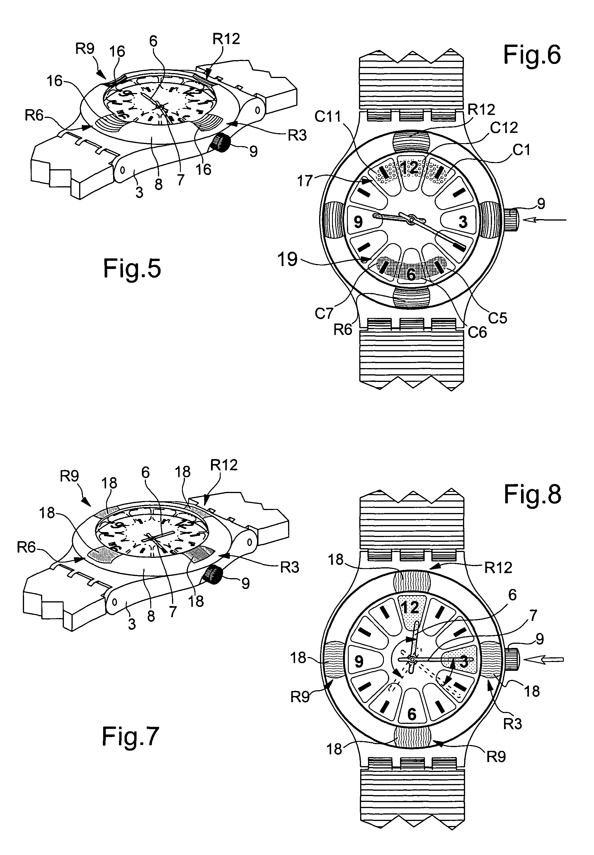
[0035]FIG. 5 shows a third embodiment in which the four markings R3, R6, R9 and R12 are formed by recessed portions 16 in the bezel, as previously contributing to easy identification of the time positions.

[0036]FIG. 6 schematically shows how to switch the alarm on (ON) and off (OFF).

[0037]FIG. 6 shows two bean shaped zones covering three consecutive sensors Ci, Ci+1, Ci+2 namely sensors C11, C12 and C1 for zone 17 corresponding to the ON state and sensors C5, C6 and C7 for zone 19 corresponding to the OFF state.

[0038]In order to switch the alarm to the ON state, the user exerts a brief application of pressure on crown 9 then puts his finger in zone 17, easily identified by marking R12 and holds it without moving in this position. The watch then emits two vibrations indicating that this state has been stored. Likewise, in order to switch the alarm to the OFF state he carries out the same manipulation by positioning his finger on zone 19 at marking R6 and holds it in this position wit...


PUM


Abstract

The timepiece, which is preferably a wristwatch, includes for each time position a capacitive sensor (C1 to C12), on a fixed bezel, including only four markings (R3, R6, R9, R12) at 3 o'clock, 6 o'clock, 9 o'clock and 12 o'clock, and a single crown-push-button (9). The case contains, in particular, a non-acoustic vibration generator (20) and an electronic interpretation and coding circuit (15), associated with a time-keeper circuit (10), with the sensors and with the crown to control the vibration device, said circuit (15) being designed to identify the manipulations on the crown (brief, long application of pressure or pull) and on the sensors (positioning or movement).

Description

[0001]This application claims priority from European Patent Application No. 02078576.2, filed Aug. 30, 2002, the entire disclosure of which is incorporated herein by reference.BACKGROUND OF THE INVENTION[0002]The present invention concerns a timepiece with touch-type reading and control of time data. The invention more particularly concerns a wristwatch enabling a user paying average attention, in conditions in which he does not want to or cannot look at the dial, without any acoustic signal perceptible to the persons near him, to find out the current time or be informed of an alarm time that can also be chosen, activated or deactivated without any visual check. This is the case, for example, of a user in conditions of reduced visibility, for example at nightfall, or a user with a visual handicap, or even a blind user.[0003]The principle of such a wristwatch, whose external appearance in no way differs from other wristwatches in which the time can be read solely visually, is already...

Claims


Application Information

Patent Timeline
IPC IPC(8): G04C13/00G04B25/04G04G21/00G04C3/00G04G21/08
CPCG04G21/08
Inventor BORN, JEAN-JACQUESFRENKEL, ERIK JAN
Owner ASULAB SA
Why Eureka
Try Eureka