Brake disc for a vehicle disc brake

Inactive Publication Date: 2006-04-25
VOLVO LASTVAGNAR AB
View PDF10 Cites 8 Cited by
  • Summary
  • Abstract
  • Description
  • Claims
  • Application Information

AI Technical Summary

Benefits of technology

[0006]The invention is based, in one embodiment, on the above described pillar design for a brake disc, but instead of arranging pillars in the hub portion as well, so that air can circulate through the entire disc from its inner periphery to its outer periph

Problems solved by technology

One disadvantage of having channels opening into the inner periphery of the hub is, however, that the material mass is reduced in that portion of the brake disc where the stresses are greatest, both as regards braking force and temperature difference.
The high stresses in connection with the holes in the hub increase the risk of cracking.

Method used


Image

  • Brake disc for a vehicle disc brake
  • Brake disc for a vehicle disc brake
  • Brake disc for a vehicle disc brake

Examples


Embodiment Construction

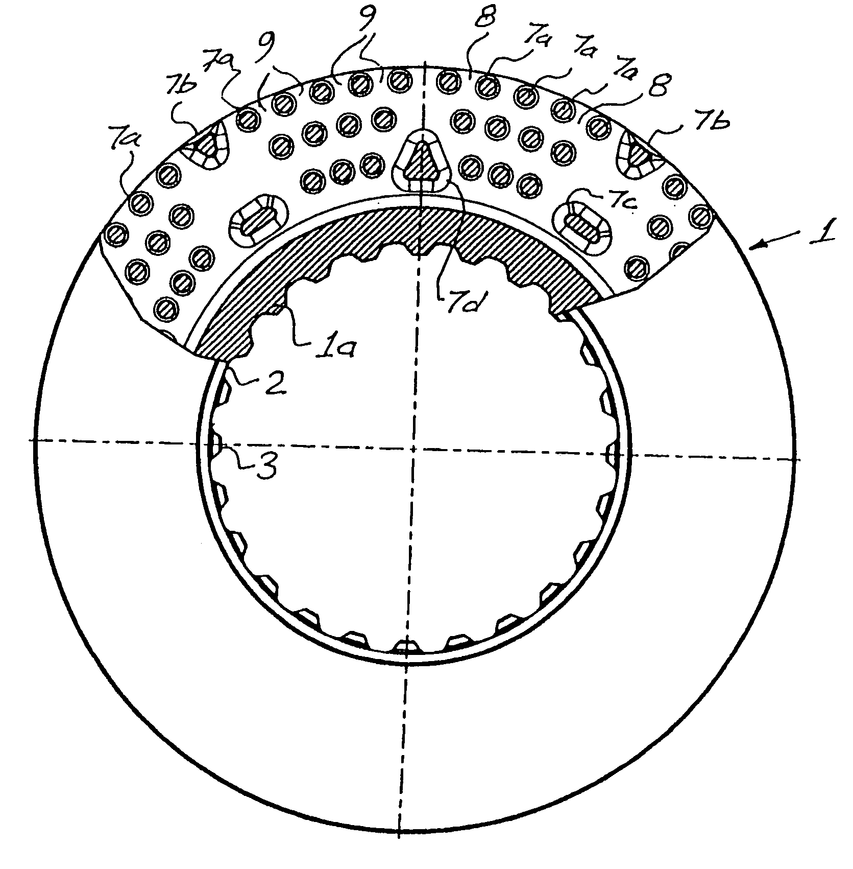
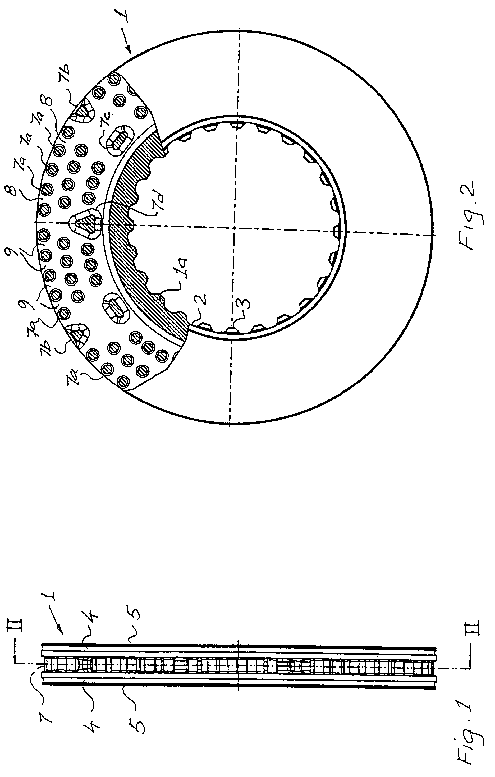
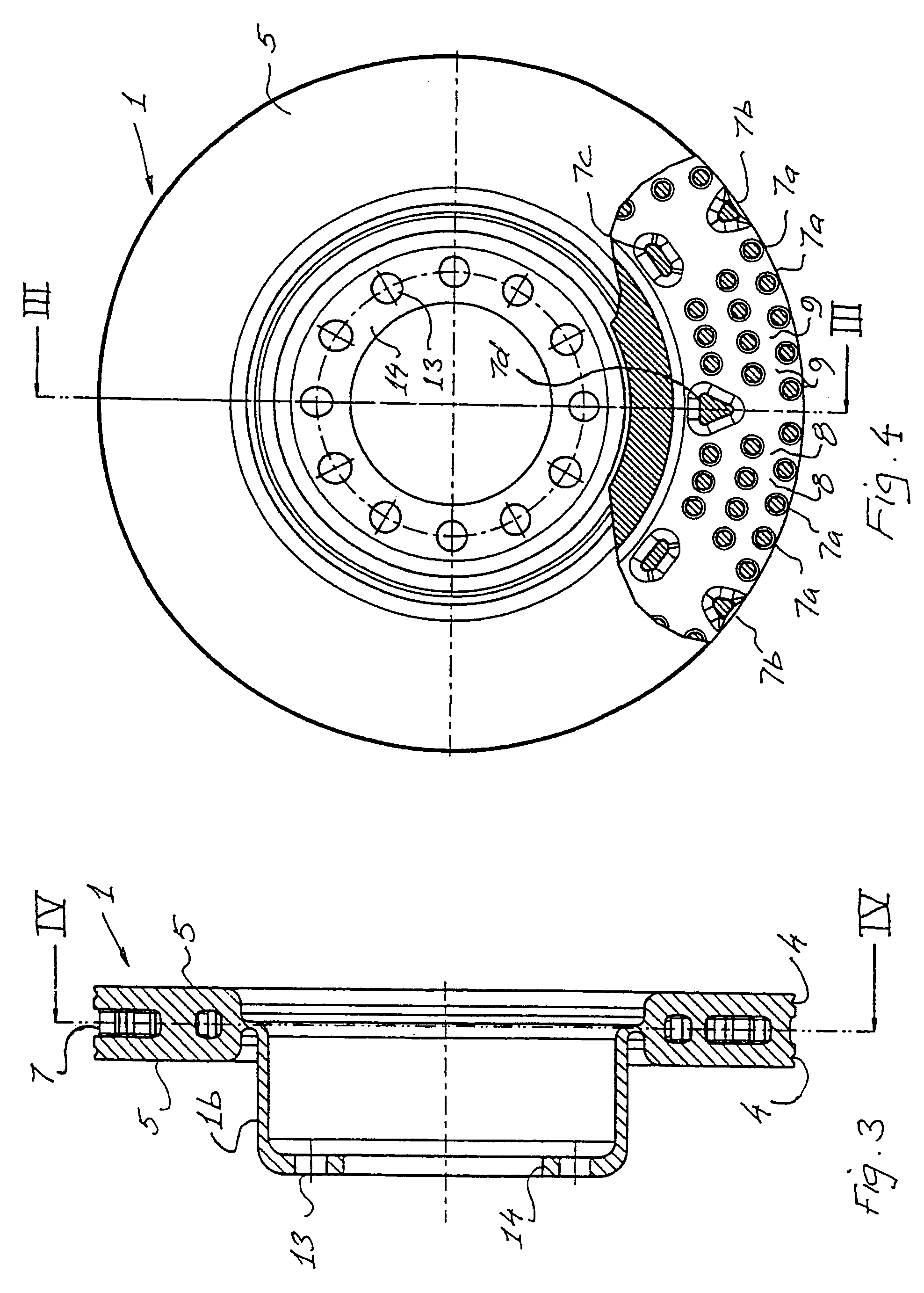
[0012]The brake disc 1 shown in FIGS. 1 and 2 has a radially inner hub portion 1a, the inner lateral surface of which is provided with splines 2, 3 intended to engage corresponding splines in a wheel hub (not shown). Examples of such non-rotatable fixation of the brake disc 1, as an alternative to a more conventional fixation whereby a holed fixing flange on the brake disc is screwed securely to a flange on the wheel hub, are shown and described in SE-A-502 189. The hub portion 1a is cast in one piece with a pair of disc elements 4 arranged with an intermediate spacing. The disc element surfaces 5 facing away from each other form the friction surfaces of the brake disc, against which brake pads (not shown) are pressed during braking. In the intermediate space 7 between the disc elements 4, there are spacer elements 7a, 7b, 7c and 7d. The spacer elements 7a–7d define passages 8 and 9 between them, through which air flows when the brake disc rotates.

[0013]The embodiment shown in FIGS....


PUM


Abstract

Brake disc for a vehicle disc brake, comprising a radially inner hub portion (1a) intended to be non-rotatably joined to a wheel hub and a surrounding, radially outer disc portion with oppositely facing friction surfaces. The outer disc portion is formed of two disc elements (4) joined to the hub portion, which are separated by spacers (7a–7d), which define passages for cooling air.

Description

BACKGROUND OF THE INVENTION[0001]The present invention relates to a brake disc for a vehicle disc brake, comprising a radially inner hub portion intended to be non-rotatably joined to a wheel hub, a surrounding, radially outer disc portion with friction surfaces facing in opposite directions, and passages disposed in the outer disc portion, said passages being arranged to guide cooling air in the disc material between the friction surfaces.DESCRIPTION OF THE RELATED ART[0002]So-called ventilated brake discs, which are made to increase the cooling effect of the ambient air by diverting heat generated during braking, occur in two principle types. One type has channels which extend radially through the disc from the inner periphery of the hub to the outer periphery of the surrounding disc portion. The channels thus have inlet openings in the inner periphery and outlet openings in the outer periphery. As the disc rotates, a guided airflow is created through the channels from the inlet t...

Claims


Application Information

Patent Timeline
IPC IPC(8): F16D65/10F16D65/12
CPCF16D65/128F16D2065/1328F16D2065/132
Inventor HULTEN, JOHANDAGH, INGEMAR
Owner VOLVO LASTVAGNAR AB
Why Eureka
Try Eureka