Engine Assembly for an Aircraft Comprising an Engine as Well as an Engine Mounting Stucture

a technology of engine and mounting stucture, which is applied in the direction of machines/engines, other domestic objects, machine supports, etc., can solve the problems of low airflow rate, achieve the effect of reducing weight, reducing weight, and improving aerodynamic performan

Inactive Publication Date: 2008-09-18
AIRBUS OPERATIONS (SAS)
View PDF10 Cites 28 Cited by
  • Summary
  • Abstract
  • Description
  • Claims
  • Application Information

AI Technical Summary

Benefits of technology

[0021]Therefore, in the non-limiting case in which the engine is intended to be suspended below the aircraft wing, this arrangement globally allows the aft engine attachment to be offset downwardly relative to the box, by means of the lower structural block which therefore forms an integral part of the rigid structure being similar to a stem or shoe. The adding of this block compared with prior art embodiments, in which the rigid structure consists solely of the box, is able to provide numerous advantages, including the advantage of spacing this same box away from the engine suspended from the engine mount. As a result, the heat conditions to which the box is subjected are far less severe than encountered previously in embodiments in which the securing interface for the aft engine attachment is located directly on the lower spar. With these less severe heat conditions, it is therefore possible to consider the use of materials less sensitive to heat for the manufacture of the rigid box, such as the composite materials already mentioned above. In said case, this can advantageously lead to a very substantial weight gain for the entire engine mount.
[0022]Additionally, it allows a separation to be made between the design of the structural block, essentially dictated by the need to ensure transmission of loads derived from the aft engine attachment, from the design of the box that is chiefly sized in relation to the wing interface it is to carry. This particular aspect implies that the block has a much smaller width than the width of the box, thereby providing a considerable advantage in terms of aerodynamic performance levels, since it is the block of small width which comes to be located in the flow of the secondary air stream, and no longer the lower part of the box of greater width. Aerodynamic disturbances directly above the aft engine attachment are therefore greatly reduced compared with those previously encountered.
[0023]Also, it is evidently to be understood that the geometry of the box is no longer influenced by the need to lie close to the engine case, since this function can be fully taken up by the lower structural block fixedly secured onto this box. The geometry of the box can therefore be considerably simplified, as can its manufacture, notably by providing a planar lower box face from one end to the other of the rigid structure. Its weight is therefore reduced and perfectly optimised, insofar as the lower part of the box advantageously no longer contains an offset of substantial width exclusively intended to bring it close to the engine case
[0024]Finally, it is indicated that since the block projects downwardly from the box and only extends over a short longitudinal length of the rigid structure, consideration can easily be given to the possible passing of conduits or similar elements through this same structural block. This option made available to the equipment of the engine mount, such as a heat exchanger system, therefore facilitates access to the aft part of the rigid structure which, in the prior art, required passing through a box having relatively difficult access.
[0025]In addition, this option is also made available to the thermal protection system of the box, whose ventilated duct can therefore be passed through the structural block, this solution forming a relatively simple manner in which to bring the aft end of the ventilated duct downstream of the aft engine attachment carried by this same block.

Problems solved by technology

However this duct, in which the airflow rate is low, only provides restricted cooling of the rigid structure and at all events is solely positioned at the forward part of the rigid box.

Method used


Image

  • Engine Assembly for an Aircraft Comprising an Engine as Well as an Engine Mounting Stucture
  • Engine Assembly for an Aircraft Comprising an Engine as Well as an Engine Mounting Stucture
  • Engine Assembly for an Aircraft Comprising an Engine as Well as an Engine Mounting Stucture

Examples


Embodiment Construction

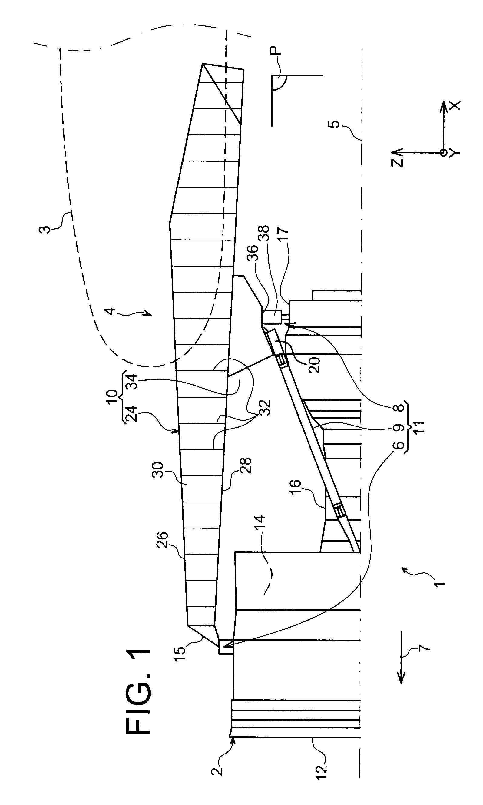
[0039]With reference to FIG. 1, an aircraft engine assembly 1 can be seen intended to be attached below a wing 3 of this aircraft, this assembly 1, provided with an engine mount 4, being in the form of a preferred embodiment of the present invention.

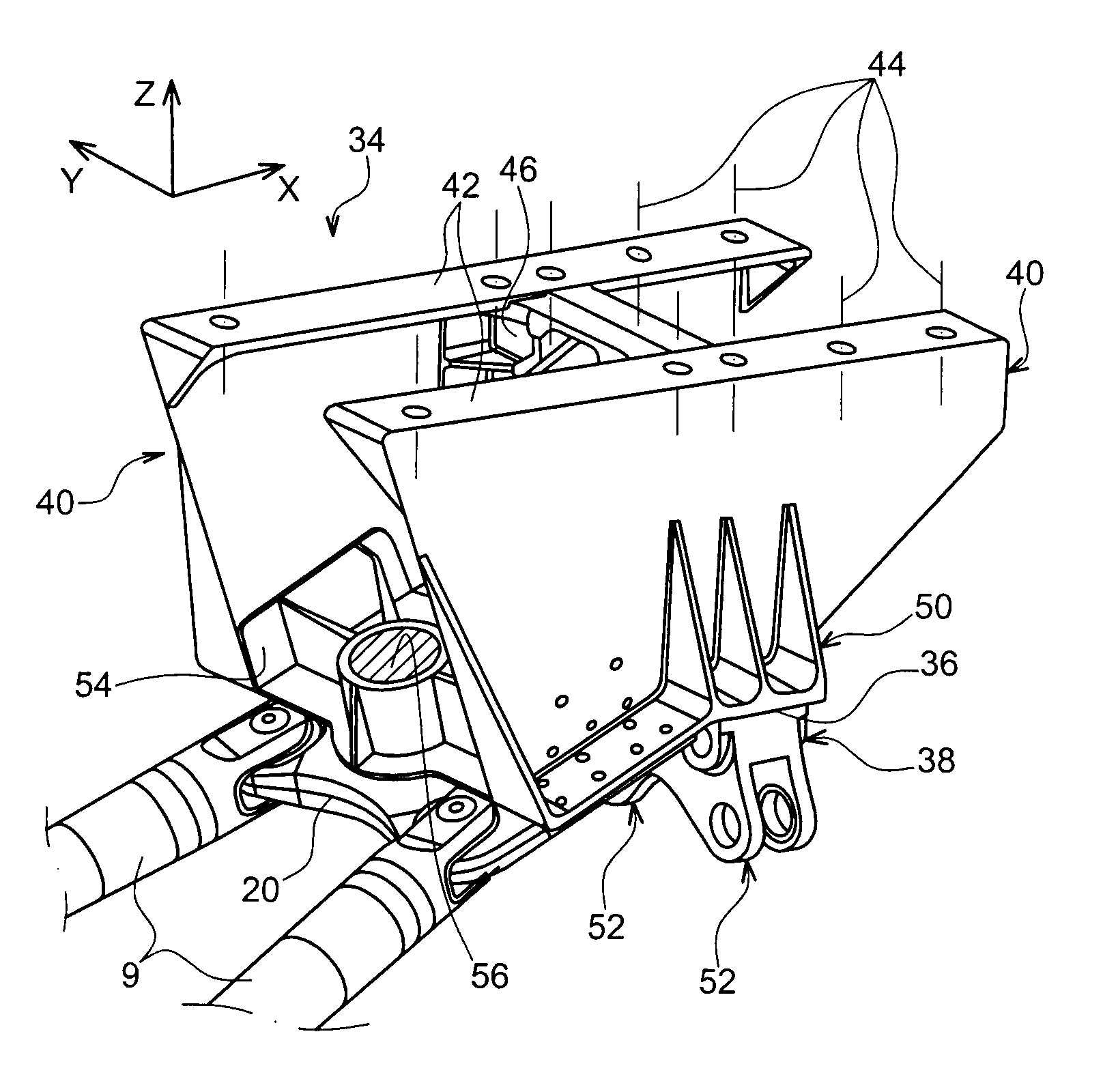
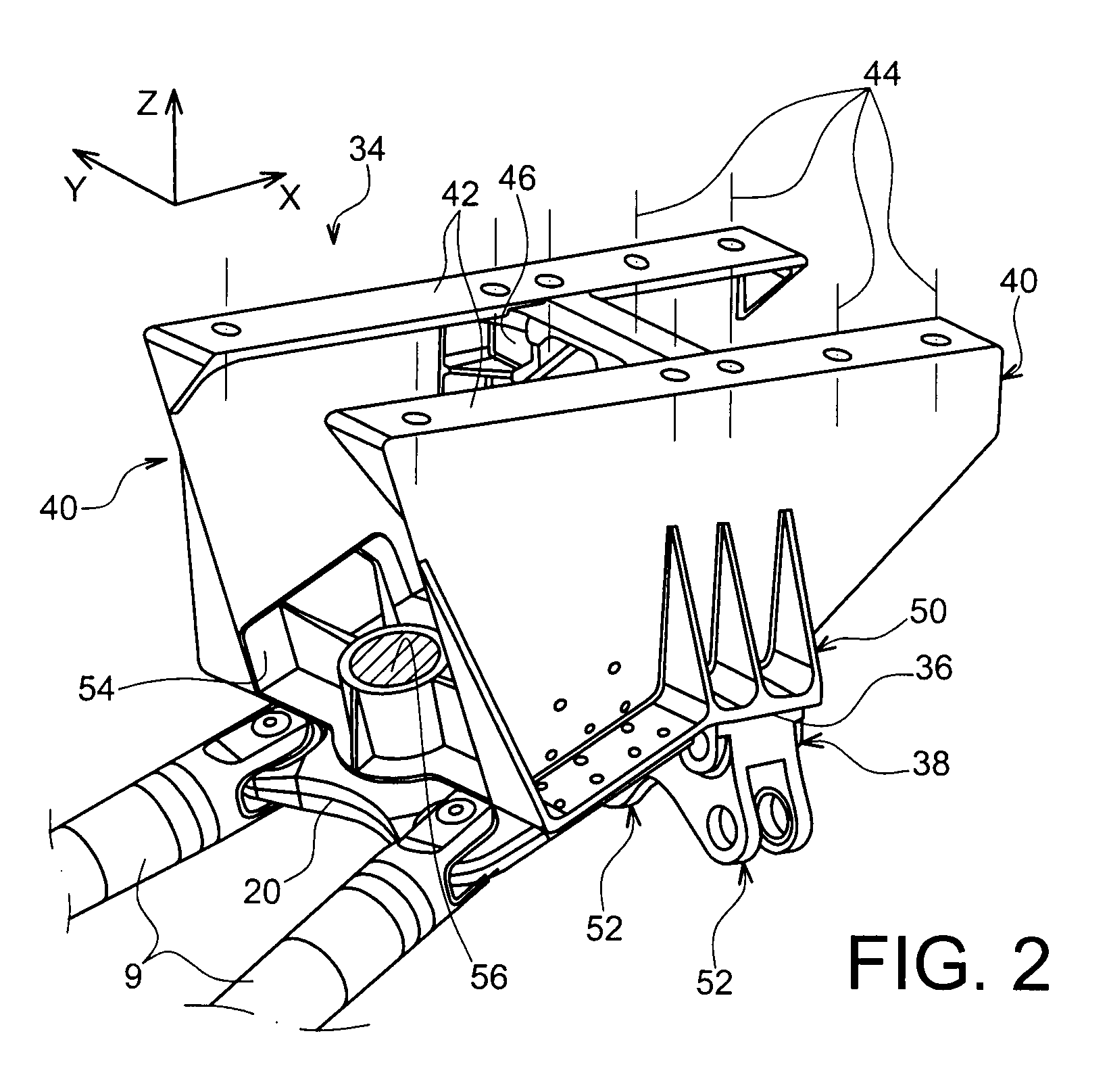
[0040]Globally, the engine assembly 1 comprises an engine such as turbojet engine 2 and the engine mount 4, this mount being notably provided with a rigid structure 10 and a mounting system 11 consisting of a plurality of engine attachments 6, 8 and a thrust mount device 9 transferring thrust loads generated by the turbojet engine 2, the mounting system 11 therefore being positioned between the engine and the above-mentioned rigid structure 10. By way of indication, it is noted that the assembly 1 is intended to be surrounded by a nacelle (not shown in this figure) and that the engine mount 4 comprises another series of attachments (not shown) used to suspend this assembly 1 below the aircraft wing.

[0041]In the remainder of the descripti...


PUM


Abstract

An engine assembly including an engine mount, the engine mount including a rigid structure including a box and a mounting system positioned between the engine and the rigid structure. This mounting system includes an aft attachment. The assembly further includes a thermal protection system for the box, including a preferably ventilated duct forming a heat barrier and extending between the box and the engine. The duct extends rearward beyond the aft engine attachment.

Description

TECHNICAL AREA[0001]The present invention generally relates to the area of engine securing pylons intended to be positioned between an aircraft wing and an engine, and more particularly to an engine assembly comprising said engine securing pylon.[0002]The invention can be used on any type or aircraft equipped with turbojet engines for example or turboprop engines.[0003]This type of securing pylon, also called <<EMS >> for Engine Mounting Structure can be used for example to suspend a turbojet engine below an aircraft wing, or to mount this turbojet engine above this same wing.STATE OF THE PRIOR ART[0004]Said engine mount is provided to form a connecting interface between an engine such as a turbojet engine and an aircraft wing. It allows the loads generated by its associated turbojet engine to be transmitted to the airframe, and also provides a path for fuel lines, electric and hydraulic systems, and air between the engine and the aircraft.[0005]To ensure load transmissi...

Claims


Application Information

Patent Timeline
Patent Type & Authority Applications(United States)
IPC IPC(8): B64D27/26
CPCB64D27/26Y02T50/44B64D2027/268Y02T50/40
Inventor LAFONT, LAURENTJOURNADE, FREDERIC
Owner AIRBUS OPERATIONS (SAS)
Why Eureka
Try Eureka