Mounting assembly for securing an engine to an aircraft wing

a technology for mounting assemblies and aircraft wings, which is applied to machines/engines, machine supports, other domestic objects, etc., can solve the problems of low airflow rate, achieve the effect of reducing weight, reducing weight, and improving aerodynamic performan

Inactive Publication Date: 2010-09-21
AIRBUS OPERATIONS (SAS)
View PDF13 Cites 33 Cited by
  • Summary
  • Abstract
  • Description
  • Claims
  • Application Information

AI Technical Summary

Benefits of technology

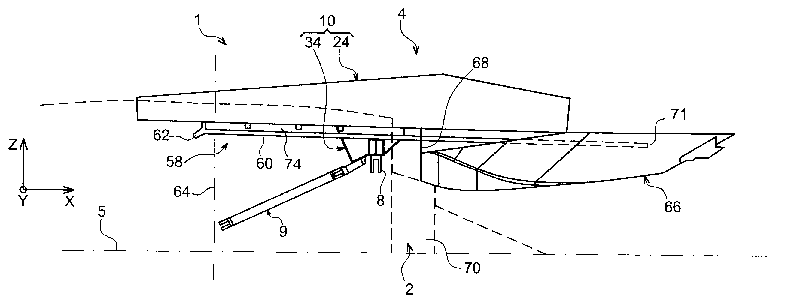
[0013]Therefore, with this arrangement according to the invention very satisfactory cooling of the box can be achieved, since it is a very large part of the lower spar which is protected by the duct, and naturally in the case of an engine which is to be suspended below the wing. The presence of this duct therefore contributes towards the possible use of a composite material to manufacture the box of the rigid structure, whose weight can therefore be largely reduced compared with the metal rigid structures of the prior art.
[0028]Finally, to further reinforce the efficacy of the thermal protection system for the box, the box can be provided with a thermal protection coating on the duct forming the heat barrier called a <<fire barrier>>, applied for example to a lower outer surface of this duct i.e. facing the engine.

Problems solved by technology

However this duct, in which the airflow rate is low, only provides restricted cooling of the rigid structure and at all events is solely positioned at the forward part of the rigid box.

Method used


Image

  • Mounting assembly for securing an engine to an aircraft wing
  • Mounting assembly for securing an engine to an aircraft wing
  • Mounting assembly for securing an engine to an aircraft wing

Examples


Embodiment Construction

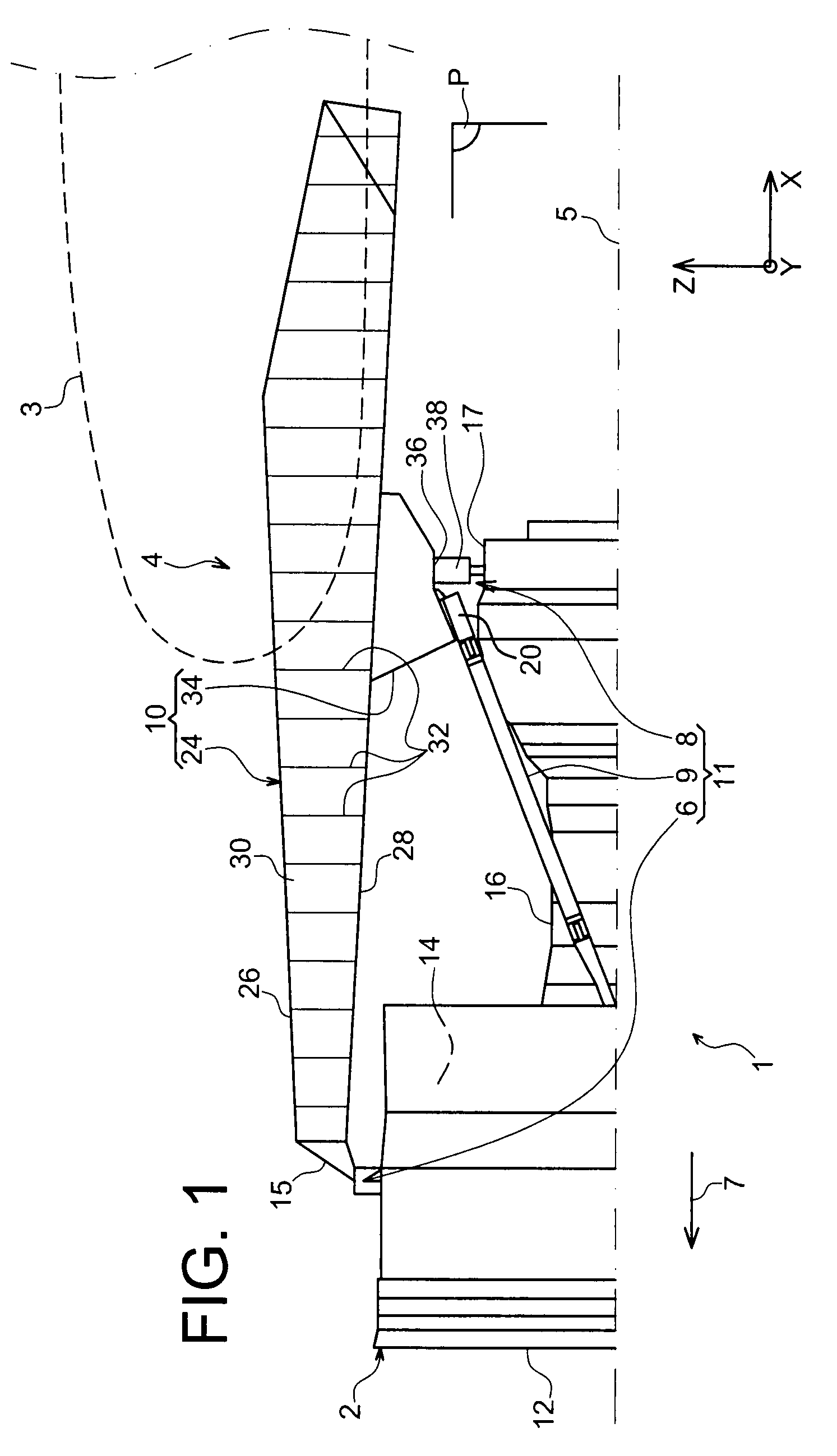
[0039]With reference to FIG. 1, an aircraft engine assembly 1 can be seen intended to be attached below a wing 3 of this aircraft, this assembly 1, provided with an engine mount 4, being in the form of a preferred embodiment of the present invention.

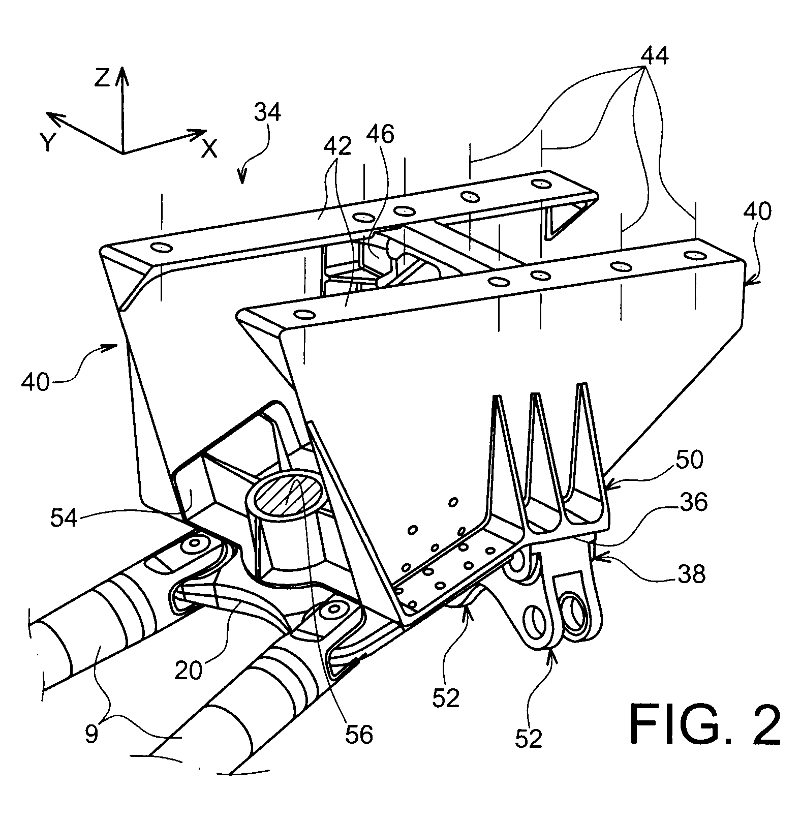
[0040]Globally, the engine assembly 1 comprises an engine such as turbojet engine 2 and the engine mount 4, this mount being notably provided with a rigid structure 10 and a mounting system 11 consisting of a plurality of engine attachments 6, 8 and a thrust mount device 9 transferring thrust loads generated by the turbojet engine 2, the mounting system 11 therefore being positioned between the engine and the above-mentioned rigid structure 10. By way of indication, it is noted that the assembly 1 is intended to be surrounded by a nacelle (not shown in this figure) and that the engine mount 4 comprises another series of attachments (not shown) used to suspend this assembly 1 below the aircraft wing.

[0041]In the remainder of the descripti...


PUM


Abstract

An engine assembly including an engine mount, the engine mount including a rigid structure including a box and a mounting system positioned between the engine and the rigid structure. This mounting system includes an aft attachment. The assembly further includes a thermal protection system for the box, including a preferably ventilated duct forming a heat barrier and extending between the box and the engine. The duct extends rearward beyond the aft engine attachment.

Description

TECHNICAL AREA[0001]The present invention generally relates to the area of engine securing pylons intended to be positioned between an aircraft wing and an engine, and more particularly to an engine assembly comprising said engine securing pylon.[0002]The invention can be used on any type or aircraft equipped with turbojet engines for example or turboprop engines.[0003]This type of securing pylon, also called <<EMS >> for Engine Mounting Structure can be used for example to suspend a turbojet engine below an aircraft wing, or to mount this turbojet engine above this same wing.STATE OF THE PRIOR ART[0004]Said engine mount is provided to form a connecting interface between an engine such as a turbojet engine and an aircraft wing. It allows the loads generated by its associated turbojet engine to be transmitted to the airframe, and also provides a path for fuel lines, electric and hydraulic systems, and air between the engine and the aircraft.[0005]To ensure load transmissi...

Claims


Application Information

Patent Timeline
Patent Type & Authority Patents(United States)
IPC IPC(8): F02C7/20
CPCB64D27/26B64D2027/268Y02T50/44Y02T50/40
Inventor LAFONT, LAURENTJOURNADE, FREDERIC
Owner AIRBUS OPERATIONS (SAS)
Why Eureka
Try Eureka