
Tool case having scabbard with adjustable length

a tool case and adjustable length technology, applied in the field of plastic cases, can solve the problems of not having a chain saw case that allows for different lengths of chain bars, no chain saw case that allows visibility, and excessively long scabbards in the cas

Inactive Publication Date: 2006-04-25
HOCHSTETLER TINA A +1
View PDF29 Cites 7 Cited by
  • Summary
  • Abstract
  • Description
  • Claims
  • Application Information

AI Technical Summary

Benefits of technology

The technical effect of this patent is that it provides a better way to transport chainsaws by shipping them with their scabs folded up and placed into a protective plastic container. This helps to keep the chainsaw safe during transit without causing any damage or injury.

Problems solved by technology

The technical problem addressed in this patent text is the need for a chain saw case that can accommodate different lengths of chain bars and allow for visibility of markings, merchandising, or branding on the chain saw bar. Additionally, the case should be easy to stack and store. Existing cases have a scabbard that extends from the case, making storage difficult.

Method used


Image

  • Tool case having scabbard with adjustable length
  • Tool case having scabbard with adjustable length
  • Tool case having scabbard with adjustable length

Examples


Embodiment Construction

[0027]Reference will now be made in detail to the preferred embodiment of the present invention, example of which is illustrated in the accompanying drawings.

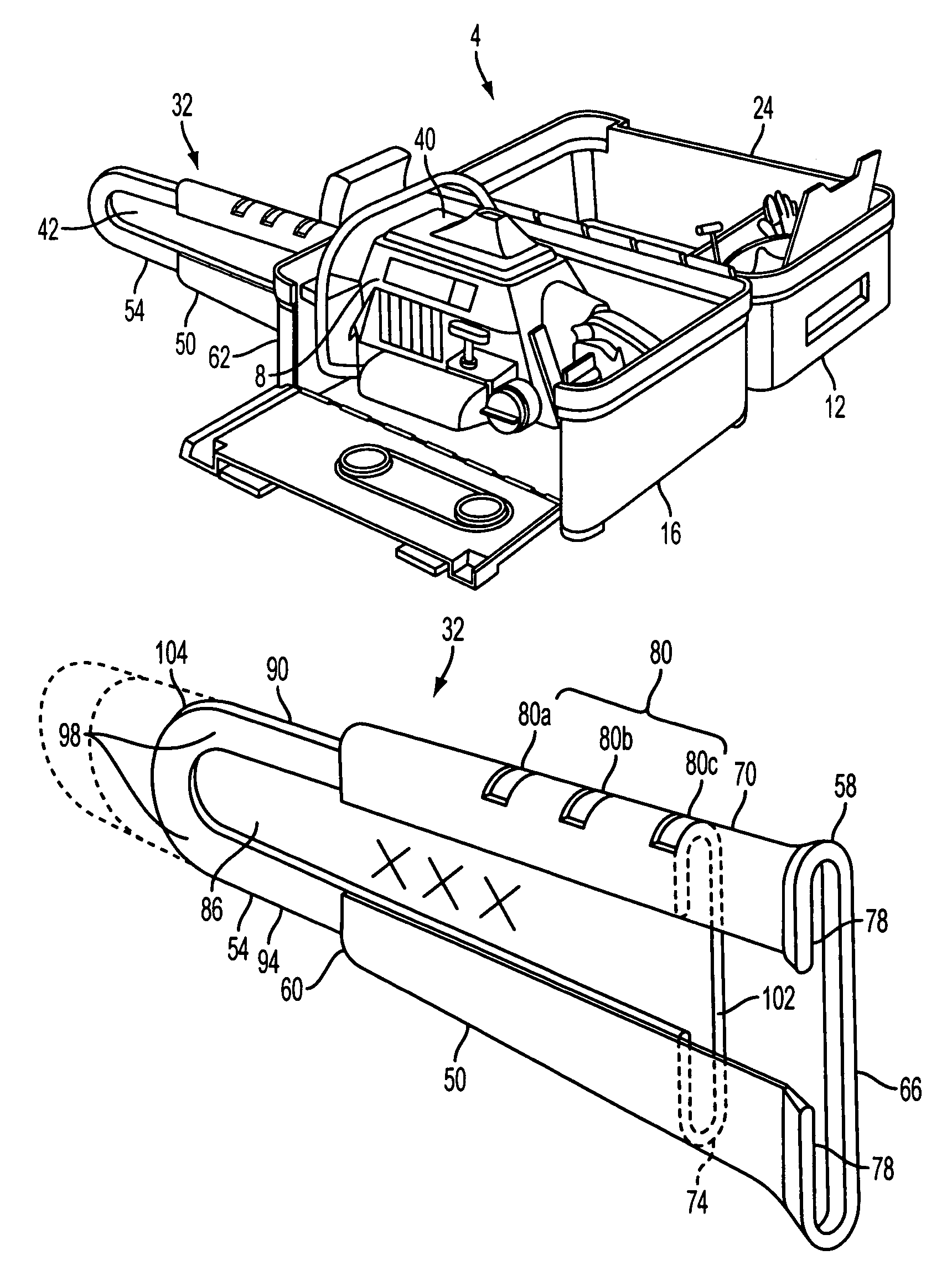
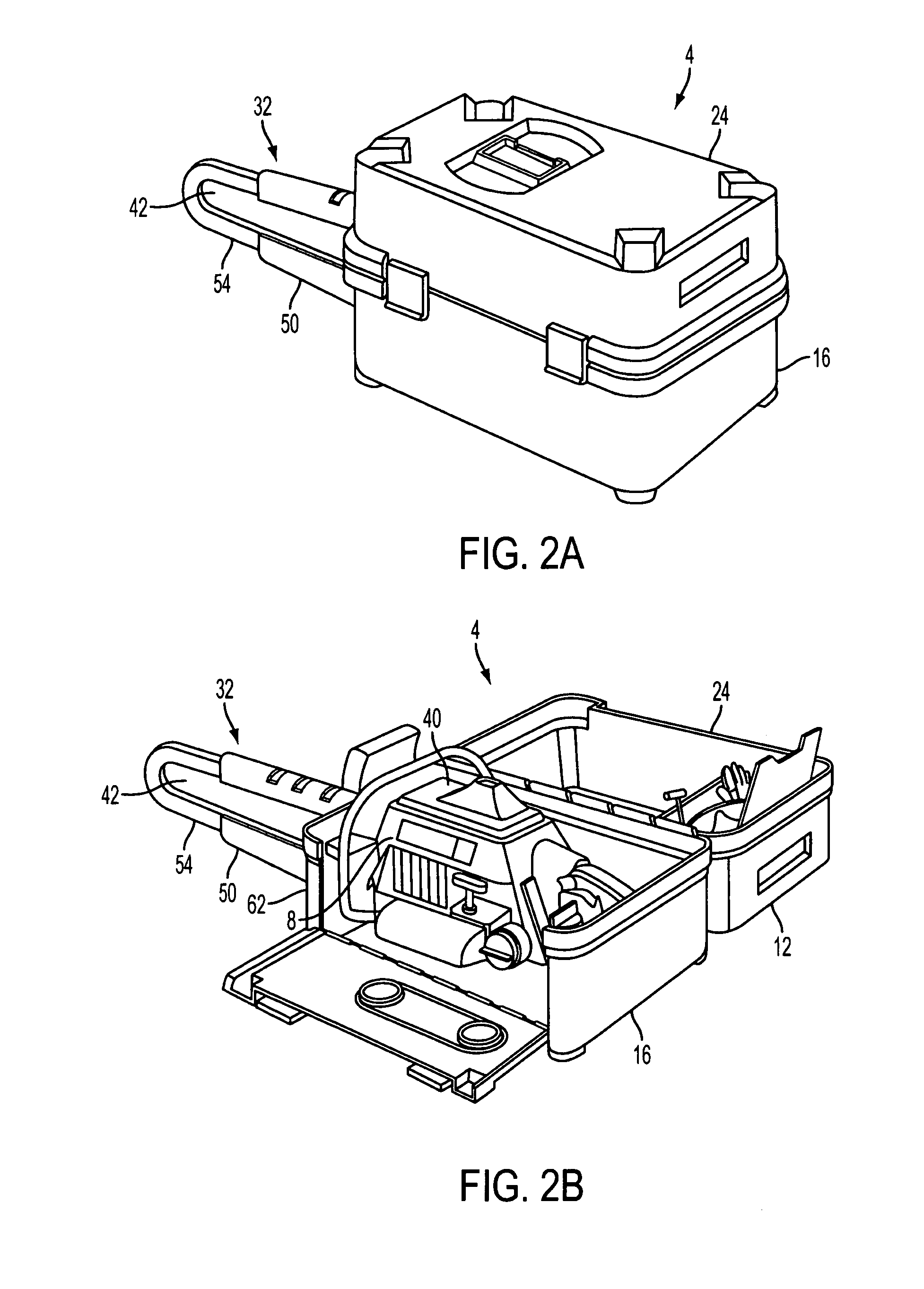
[0028]As shown in FIGS. 2A and 2B, a case 4 for housing a chain saw 8 includes a main compartment 12 formed of a base 16, and a cover 24. The case further includes a scabbard 32 for housing the chain bar of a chain saw 8.

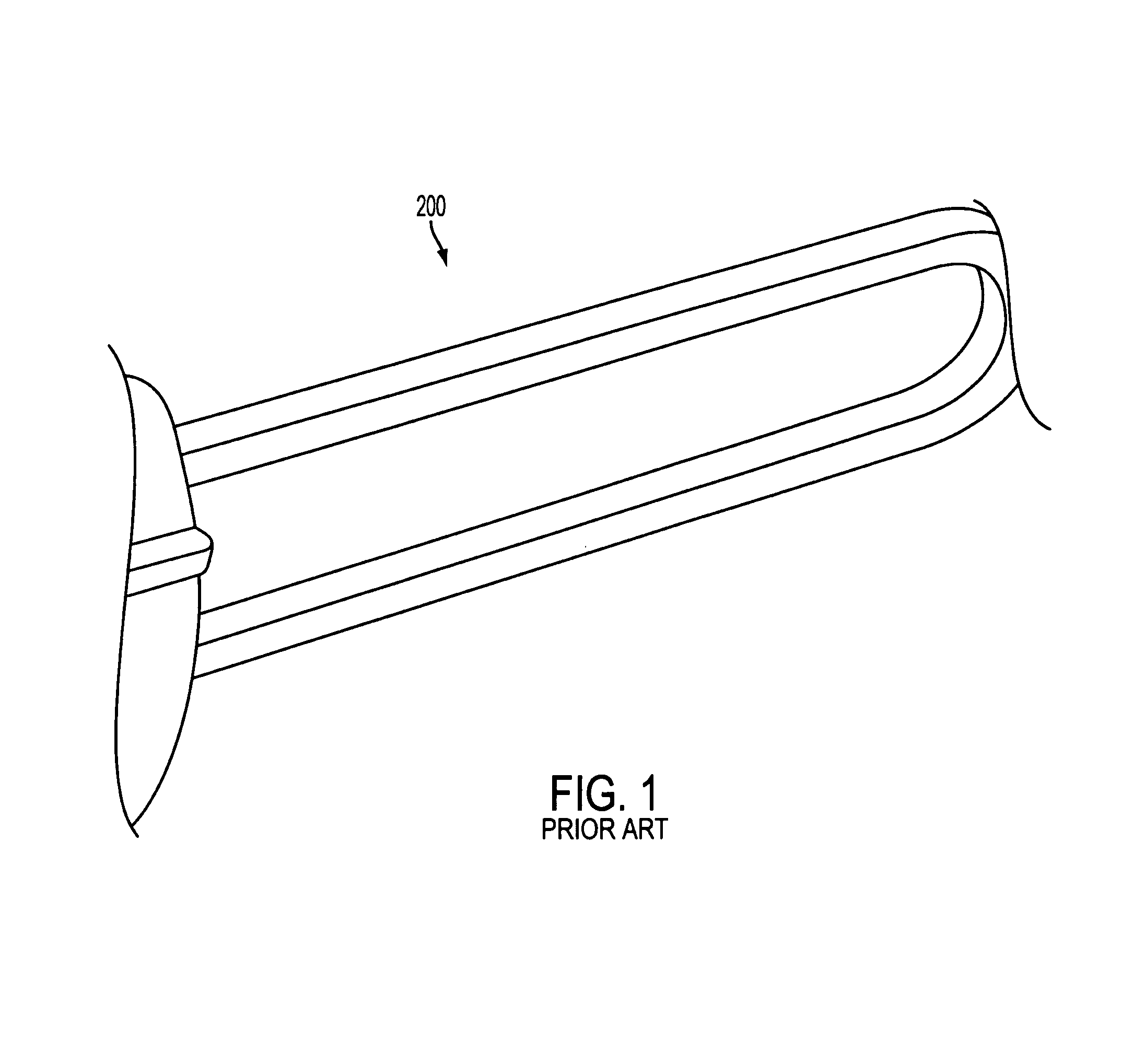
[0029]As shown in FIG. 2B, a conventional chain saw 8 includes a main chain saw portion 40 and a chain saw bar 42 (partially shown). The chain bar portion is shown in more detail in FIG. 2.

[0030]The scabbard 32 is hollow to hold the chain bar 42 therein. The scabbard 32 includes a first scabbard portion 50 and a second scabbard portion 54, as shown in FIG. 3. The first scabbard portion 50 has a proximal end 58 and a distal end 60.

[0031]The proximal end 58 of the first scabbard portion 50 engages a slot 20 in the side wall 62 of the main compartment 12 of the case 4. The first scabbard portion 50 can also be rem...


PUM


Abstract

A chain saw case has an adjustable scabbard that telescopes to allow for different lengths of chain bar. The scabbard also has an opening along one side to allow visibility of the side of the chain saw bar and any markings, including branding, on the chain saw bar. The chain saw case is designed to be fabricated using injection-molding techniques. Because the scabbard collapses, and the injection molded case offers ample space not afforded in all existing blow molded chain saw cases, the scabbard can be placed inside the case during shipment reducing shipping cost and space required while in distribution.

Description


Claims


Application Information

Patent Timeline
Owner HOCHSTETLER TINA A
Learn More