Hydraulic actuator assembly with rotation restraint

a technology of rotating restraint and actuator, which is applied in the direction of positive displacement engines, mechanical equipment, machines/engines, etc., can solve the problems of loss of hydraulic fluid, large assembly size, and large volume of the actuator assembly

Inactive Publication Date: 2006-04-25
HELDER BRUCE A
View PDF29 Cites 16 Cited by
  • Summary
  • Abstract
  • Description
  • Claims
  • Application Information

AI Technical Summary

Benefits of technology

[0015]The second actuator can have an end cap that is non-rotatable about the second longitudinal axis, with the anti-rotation rod rigidly attached to the end cap for insertion in the axial bore and restrained from rotational movement about the second longitudinal axis. The non-rotation mounting can further comprise a rod insert that is non-rotatably attached to the second piston rod within the second cylinder, the rod insert having a non-circular aperture coaxial with the second longitudinal axis and complementary to the cross-section of the anti-rotation rod, and the anti-rotation rod slidably received in the non-circular aperture of the rod insert to prevent rotation of the second piston rod relative to the anti-rotation rod.

Problems solved by technology

When the transit mixer travels down the road, the dual actuator is free to swing back and forth, which can seriously damage the actuator assembly and render the transit mixer unusable.
It can also cause hydraulic connecting hoses attached to the cylinders to be pulled loose, resulting in the loss of hydraulic fluid.
However, this assembly is very bulky and heavy, and subject to external damage.
Furthermore, the assembly requires constant greasing and maintenance.
The cylinder is regularly covered with cement dust which collects between the solid bar and the hollow tube, and causes them to stick together and / or travel inconsistently.
Unless greasing and maintenance are performed regularly, the buildup of cement dust can harden, and the device can consequently break or no longer function properly.
The device is also subject to the intrusion of water, leading to rusting which can also cause it to prematurely fail.
This device is also difficult to mount on the mixer, as the alignment between the non-rotational rod mount and the cylinder mount is critical and difficult to keep in alignment during installation.
The device is also difficult to manufacture and therefore costly.

Method used


Image

  • Hydraulic actuator assembly with rotation restraint
  • Hydraulic actuator assembly with rotation restraint
  • Hydraulic actuator assembly with rotation restraint

Examples


Embodiment Construction

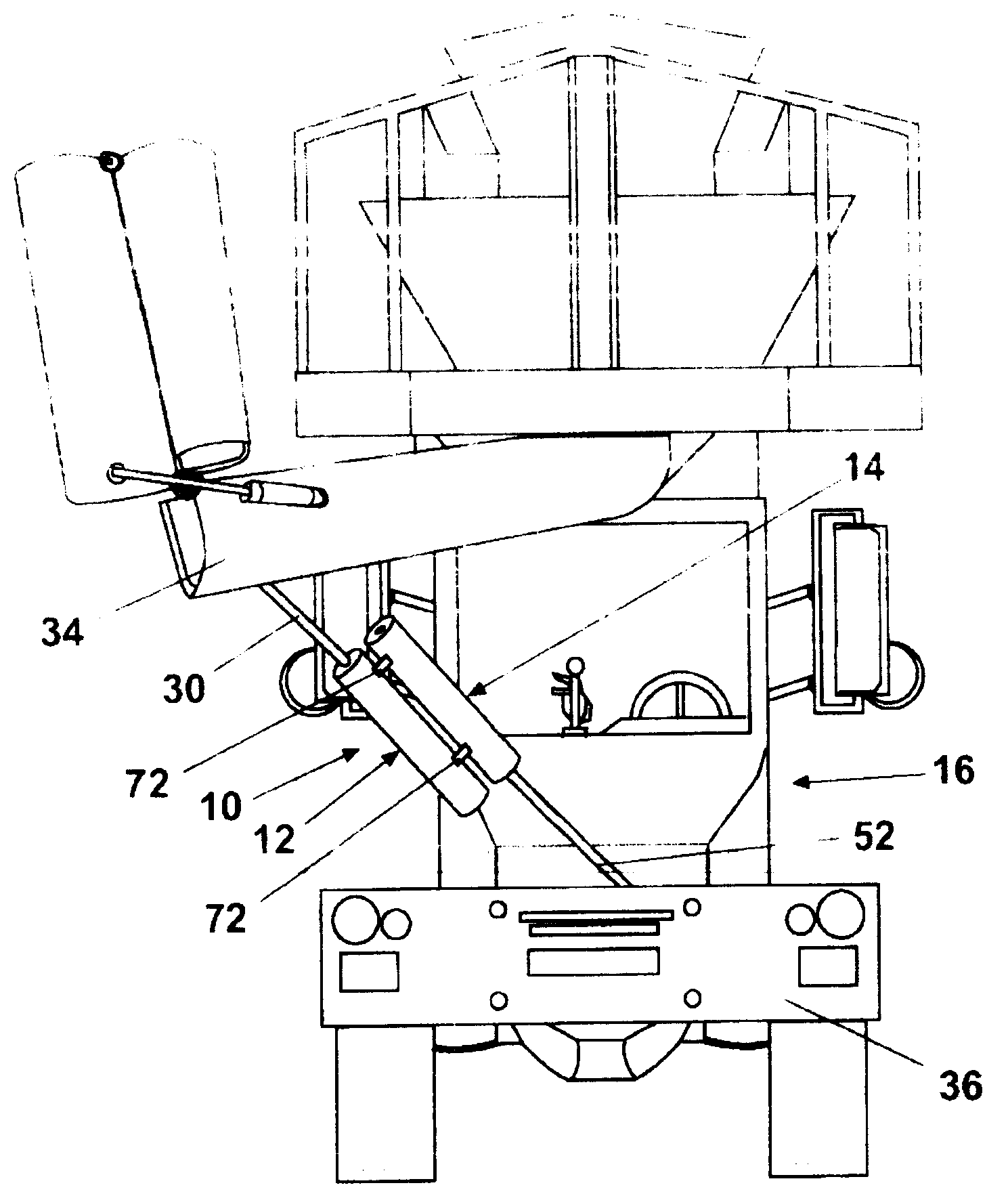
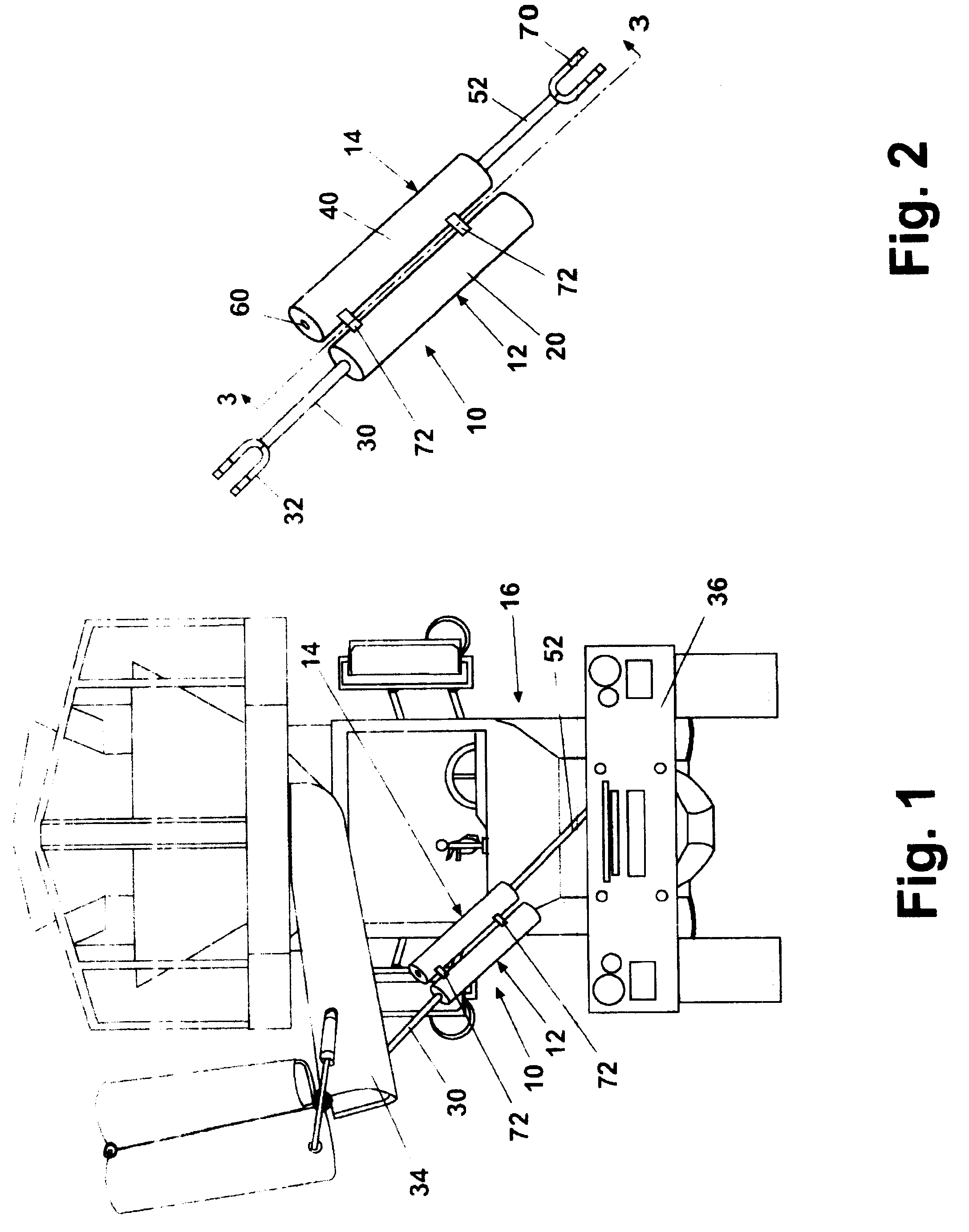
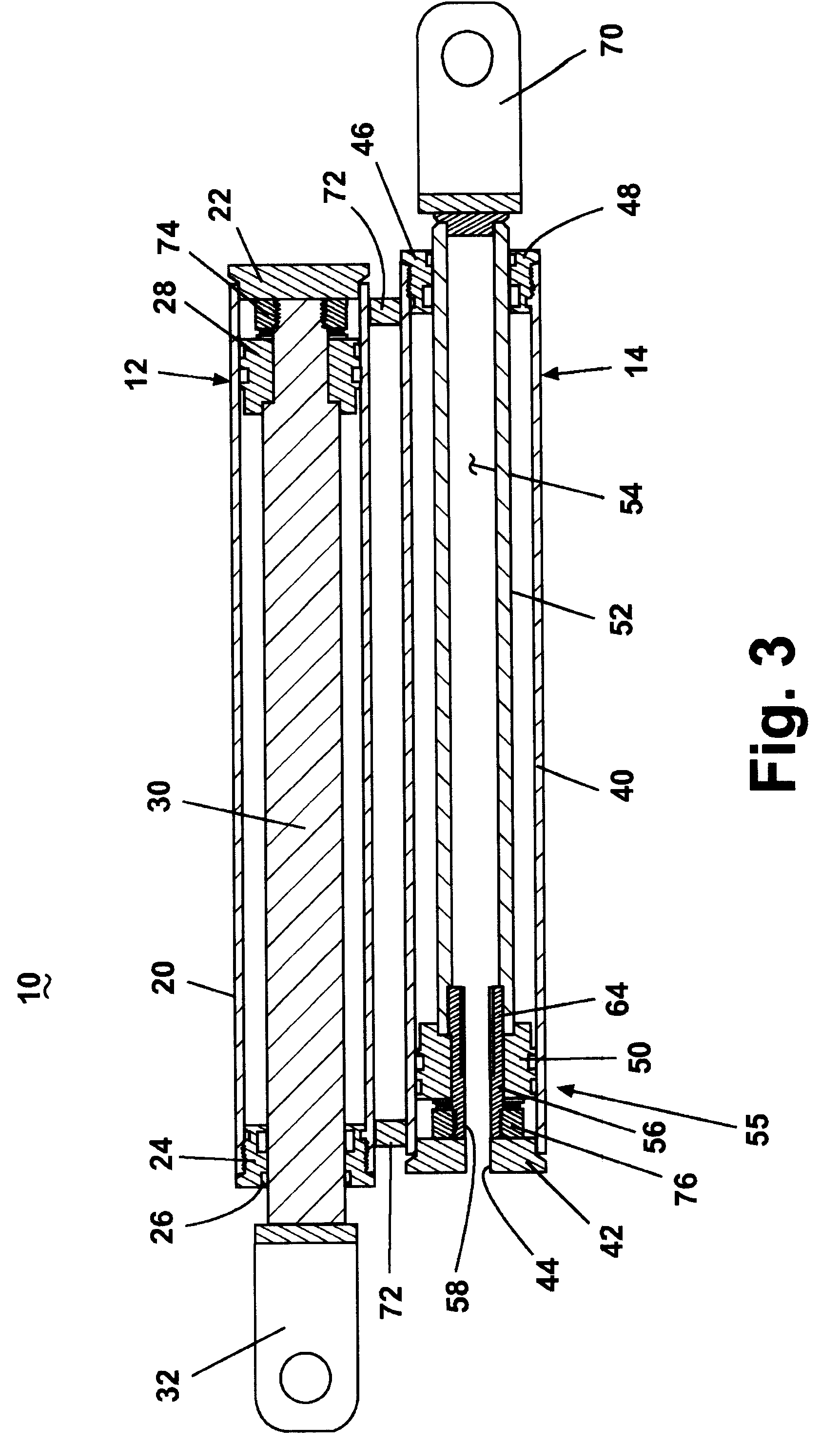
[0025]Referring now to the drawings, and to FIG. 1 in particular, according to the invention a non-rotational dual hydraulic actuator assembly 10 comprises two hydraulic actuators 12, 14 that are ganged together for extension of their respective piston rods 30, 52 in opposite directions wherein at least one of the actuators comprises a mechanism that prevents rotation of the actuator assembly 10 about its longitudinal axis. FIG. 1 illustrates the hydraulic actuator assembly 10 incorporated into a concrete mixer truck 16 for positioning of a moveable concrete delivery chute 34. A first piston rod 30 of the dual hydraulic actuator assembly 10 is attached to the delivery chute 34 and a second piston rod 52 is attached to a suitable anchor point on the transit mixer chassis, such as a bumper 36, a frame element, or the like. As shown also in FIGS. 2 and 3, the hydraulic actuator assembly 10 comprises a pair of cylinders 20, 40 rigidly ganged together through a suitable rigid mounting 72...


PUM

PropertyMeasurementUnit
pressureaaaaaaaaaa
rotationaaaaaaaaaa
distanceaaaaaaaaaa

Abstract

A hydraulic actuator assembly comprises a pair of hydraulic actuators having cylinders, pistons, and piston rods that are ganged together for extension of their respective piston rods in longitudinally opposite directions wherein at least one of the actuators comprises an anti-rotation mechanism that prevents rotation of the actuator assembly about its longitudinal axis. The anti-rotation mechanism comprises an axial anti-rotation rod rigidly attached to a cylinder having a non-circular cross-section slidably complementary to a non-circular aperture in a hollow piston rod. The piston rod can travel longitudinally along the anti-rotation rod, but is prevented from rotating by the non-circular cross-section.

Description

CROSS REFERENCE TO RELATED APPLICATIONS[0001]This application claims the benefit of U.S. provisional application Ser. No. 60 / 319,650, filed Oct. 25, 2002, which is incorporated herein in its entirety.BACKGROUND OF INVENTION[0002]1. Field of the Invention[0003]The invention relates generally to hydraulic actuator assemblies. In one of its aspects, the invention relates to a pair of hydraulic actuators rigidly ganged together wherein the piston rods of the cylinders are extendible in parallel, longitudinally opposed directions. In another aspect, the invention relates to a hydraulic actuator assembly comprising a pair of hydraulic actuators rigidly ganged together wherein at least one of the piston rods is prevented from rotating relative to the hydraulic cylinder in which it is reciprocally mounted. In another aspect, the invention relates to a hydraulic actuator assembly comprising a pair of hydraulic actuators rigidly ganged together in which at least one of the piston rods is prev...

Claims


Application Information

Patent Timeline
Patent Type & Authority Patents(United States)
IPC IPC(8): B28C5/42B60P1/40F15B15/14
CPCB28C5/4248F15B15/1419F15B15/1404B60P1/40
Inventor HELDER, BRUCE A.
Owner HELDER BRUCE A
Why Eureka
Try Eureka