Injection unit for an injection moulding machine

a technology of injection unit and injection moulding machine, which is applied in the direction of dynamo-electric machines, food shaping, food science, etc., can solve the problems of disadvantages of comparatively large overall axial length of such injection units, and achieve the effect of high injection speed and compact overall length

Inactive Publication Date: 2006-04-25
MANNESMANN PLASTICS MACHINERY
View PDF3 Cites 17 Cited by
  • Summary
  • Abstract
  • Description
  • Claims
  • Application Information

AI Technical Summary

Benefits of technology

[0011]The object of the present invention is to improve an injection unit of the generic type to the extent that it has a particularly compact overall length, that is as short as possible in the axial direction, while having a very high injection speed, in particular for producing relatively small to medium-sized injection-molded parts.
[0012]The invention is based on an injection unit for an injection-molding machine for processing plastics or other plasticized materials which has a screw which is provided with a rotational drive by means of a rotating motor having a stator and a rotor and can be moved by a number of electrical linear motors in each case comprising a primary part, which functions as a stator, and a secondary part, which is linearly movable with respect to said primary part. In this case, the linear motors are assembled to form a housing-like group with the secondary parts of the linear motors arranged parallel to one another and the secondary parts of the linear motors coupled to the screw for drive purposes, so that linear drive forces can be transferred to the screw. According to the invention, it is provided that the rotating motor, fixedly connected to the screw in the axial direction, is arranged within the housing-like group and, with its stator, is fixedly coupled in the axial direction to the secondary parts of the linear motors. In this way, the overall axial length of the injection unit is distinctly reduced.
[0015]It is advantageous to assemble the secondary parts of the linear motors by connecting elements to form a self-supporting assembly.

Problems solved by technology

The comparatively great overall axial length of such an injection unit can be seen as a disadvantage.

Method used


Image

  • Injection unit for an injection moulding machine
  • Injection unit for an injection moulding machine
  • Injection unit for an injection moulding machine

Examples


Embodiment Construction

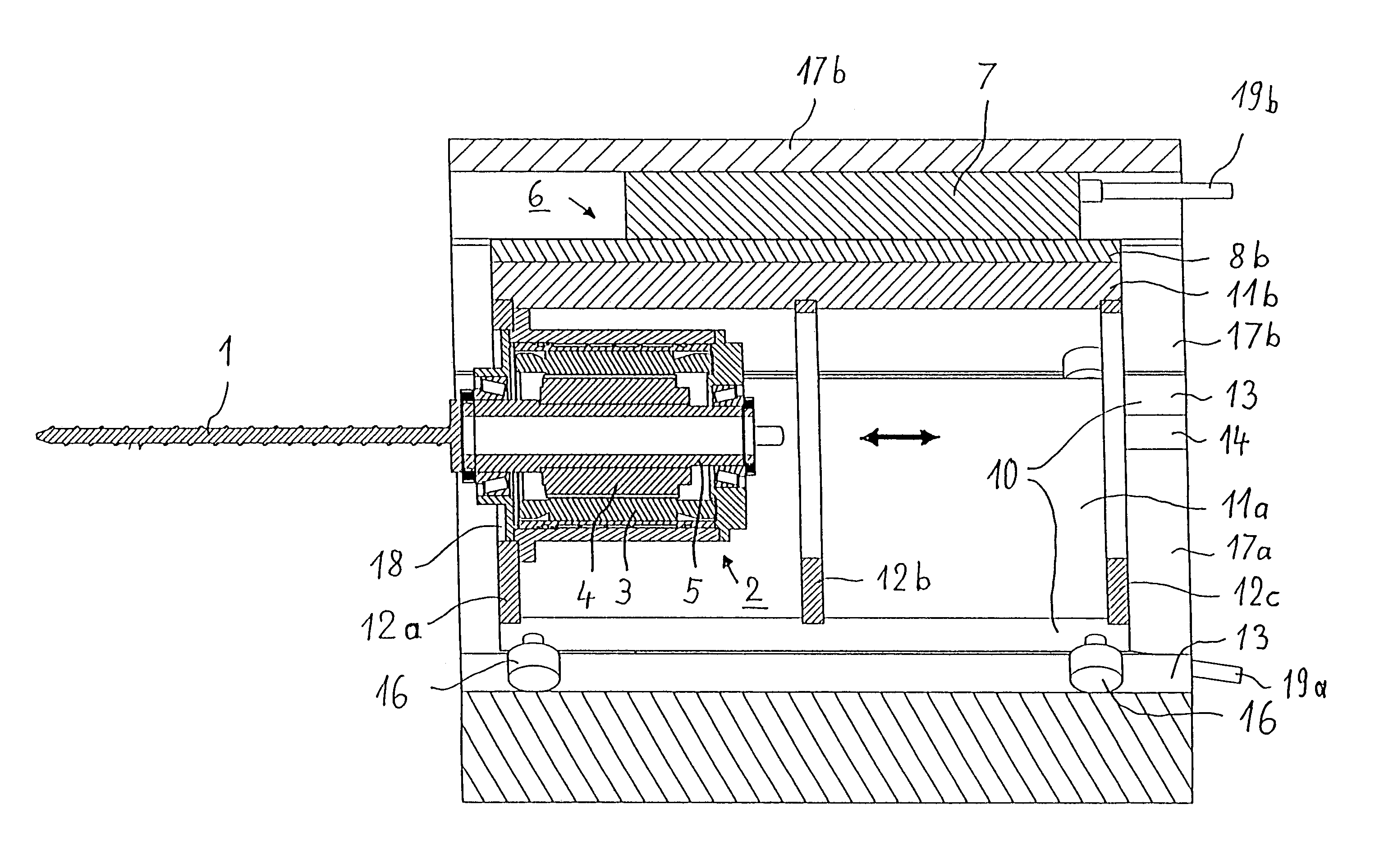
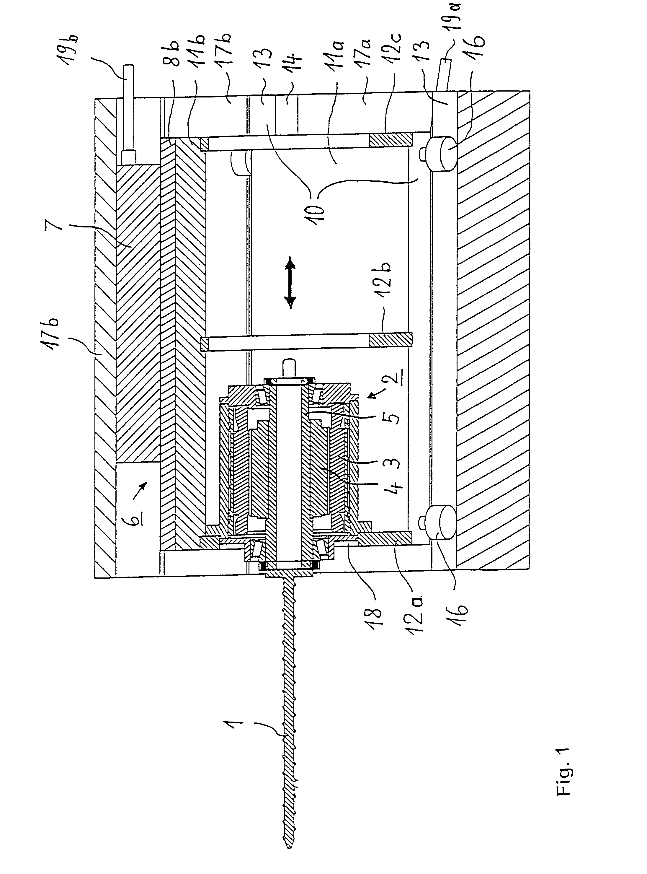
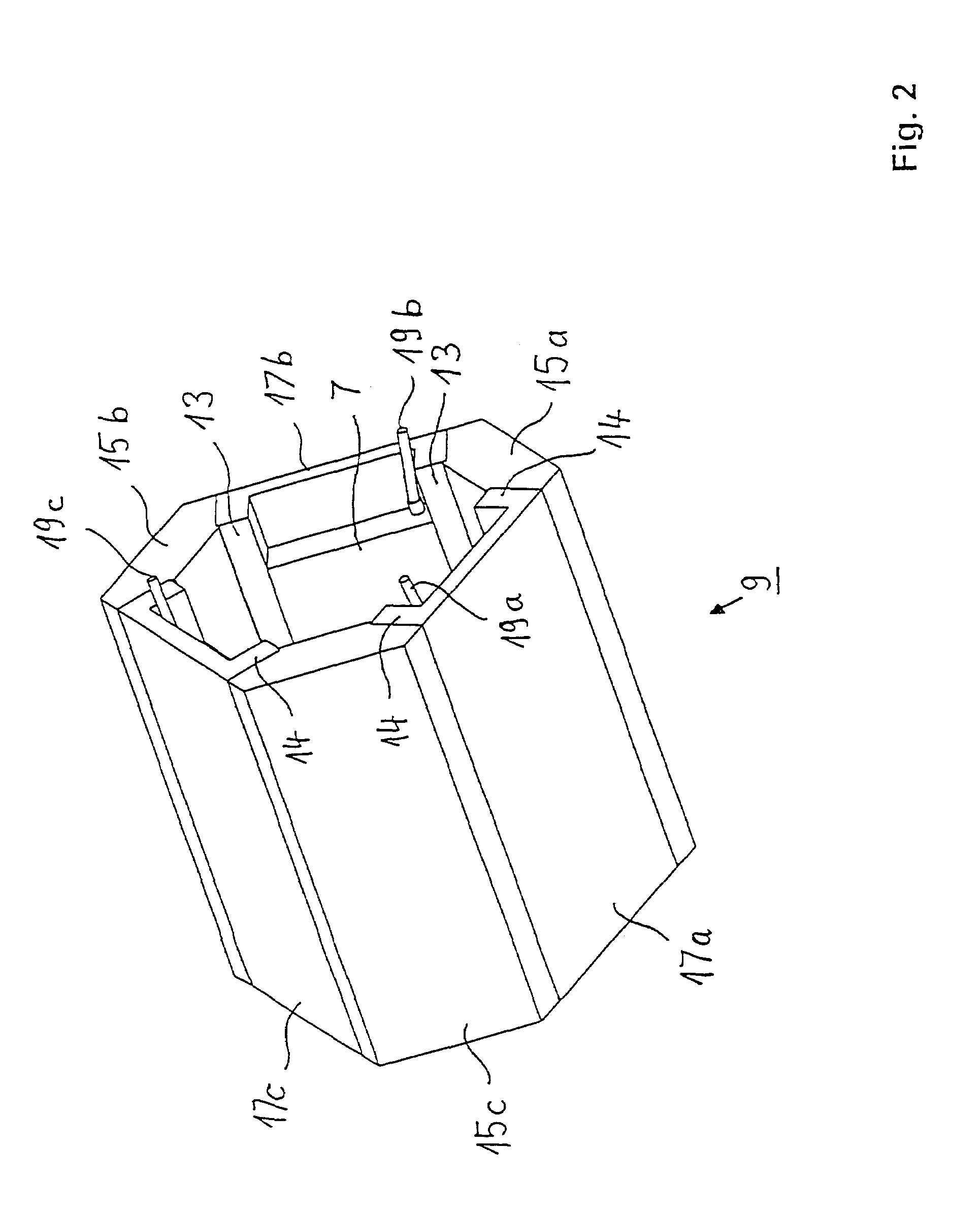
[0024]The injection unit according to the invention, represented in various views and sections in FIGS. 1 to 4, has a screw 1, which is connected to the rotor 4 of an electrical hollow-shaft motor 2 having a stator 3 and a hollow shaft 5. The hollow-shaft motor 2 is connected with its housing, and consequently also with its stator 3, in a rotationally fixed manner by means of a transverse carrier 12a, formed as a plate, to an assembly which is formed by three secondary parts 8a, b, c, i.e. the movable parts of three electrical linear motors 6. This structural unit can be seen particularly well in a separate representation in FIG. 3. The secondary parts 8a, b, c are mounted in respective flat carriers 11a, b, c, which have the cross-sectional form of a very flat U. The carriers 11a, b, c are connected to one another by three transverse carriers 12a, b, c arranged one behind the other at axial intervals. As can already be clearly seen from FIG. 1, the hollow-shaft motor 2 is arranged ...


PUM

PropertyMeasurementUnit
pressureaaaaaaaaaa
shapeaaaaaaaaaa
lengthaaaaaaaaaa

Abstract

An injection screw is rotationally driven by a rotating motor having a stator and a rotor and can be moved by a number of electrical linear motors, linear motor comprising a primary part, which functions as a stator, and a secondary part, which is linearly movable in the axial direction in a screw cylinder to execute the injection function. The primary parts are assembled to form a first housing-like unit and the secondary parts are assembled to form a second housing-like unit which is coupled to the screw for drive purposes. The rotating motor, fixedly connected to the screw in the axial direction, is arranged with its stator fixedly coupled in the axial direction to the secondary housing-like unit.

Description

PRIORITY CLAIM[0001]This is a U.S. national stage of application No. PCT / DE01 / 04593, filed on Dec. 03, 2001. Priority is claimed on that application on the following application: Country: Germany, Application No.: 100 61 329.2, Filed: Dec.04, 2000.BACKGROUND OF THE INVENTION[0002]1. Field of the Invention[0003]The invention relates to an injection unit for an injection-molding machine for processing plastics or other plasticized materials.[0004]2. Description of the Related Art[0005]Injection-molding machines for processing thermoplastic materials, for example, have been known for many years. In such an injection-molding machine, usually plastics pellets are heated up and melted in a heated plasticizing cylinder, in which a screw rotates, and the melt is subsequently injected under high pressure into the cavity of an injection mold. The molten plastics material is then cooled down, so that it solidifies and is given its final shape. The cooled-down injection-molded parts are ejected...

Claims


Application Information

Patent Timeline
Patent Type & Authority Patents(United States)
IPC IPC(8): B29C45/77B29C45/50H02K7/06H02K41/00
CPCB29C45/5008H02K7/06B29C2045/5024B29C2045/1793
Inventor BECKER, KLAUSMEYER, RALF INGOWEINMANN, ROBERT
Owner MANNESMANN PLASTICS MACHINERY
Why Eureka
Try Eureka