Hand sander vacuum attachment

a sander and vacuum attachment technology, applied in the field of hand-operated sanders, can solve the problems of limiting the user's options as to the availability of sanders, sanding tools that cannot be used for close-in edge sanding, and many of the known sanders have no adjustment capability

Active Publication Date: 2006-04-25
SHOP VAC
View PDF56 Cites 31 Cited by
  • Summary
  • Abstract
  • Description
  • Claims
  • Application Information

AI Technical Summary

Benefits of technology

[0003]Thus, in one aspect of the present disclosure, there is a manual sander apparatus having a lower sanding backer plate with front end and rear end fastener means for holding configured spring metal clamp members in place against the backside of that backer plate. These clamps hold down and maintain taughtness of the respective tail ends of the underlying sandpaper sheet. There is also a configured, generally hollow upper body portion, which mates with the backer plate, and which has a surrounding skirt section with front and rear lower skirt extensions. The body portion is held in place against the sanding backer plate by a threaded fastener. A slotted opening formed in an interior platform area on the upper handle body portion, in conjunction with a threaded fastener holding that upper body portion to the lower sanding backer plate, permits either centered positioning, or re

Problems solved by technology

Many of such known sanding tools have no capability of adjustment, such that the sanding tool cannot be used for close-in edge-sanding purposes.
This greatly limits the user's options as to avai

Method used


Image

  • Hand sander vacuum attachment
  • Hand sander vacuum attachment
  • Hand sander vacuum attachment

Examples


Embodiment Construction

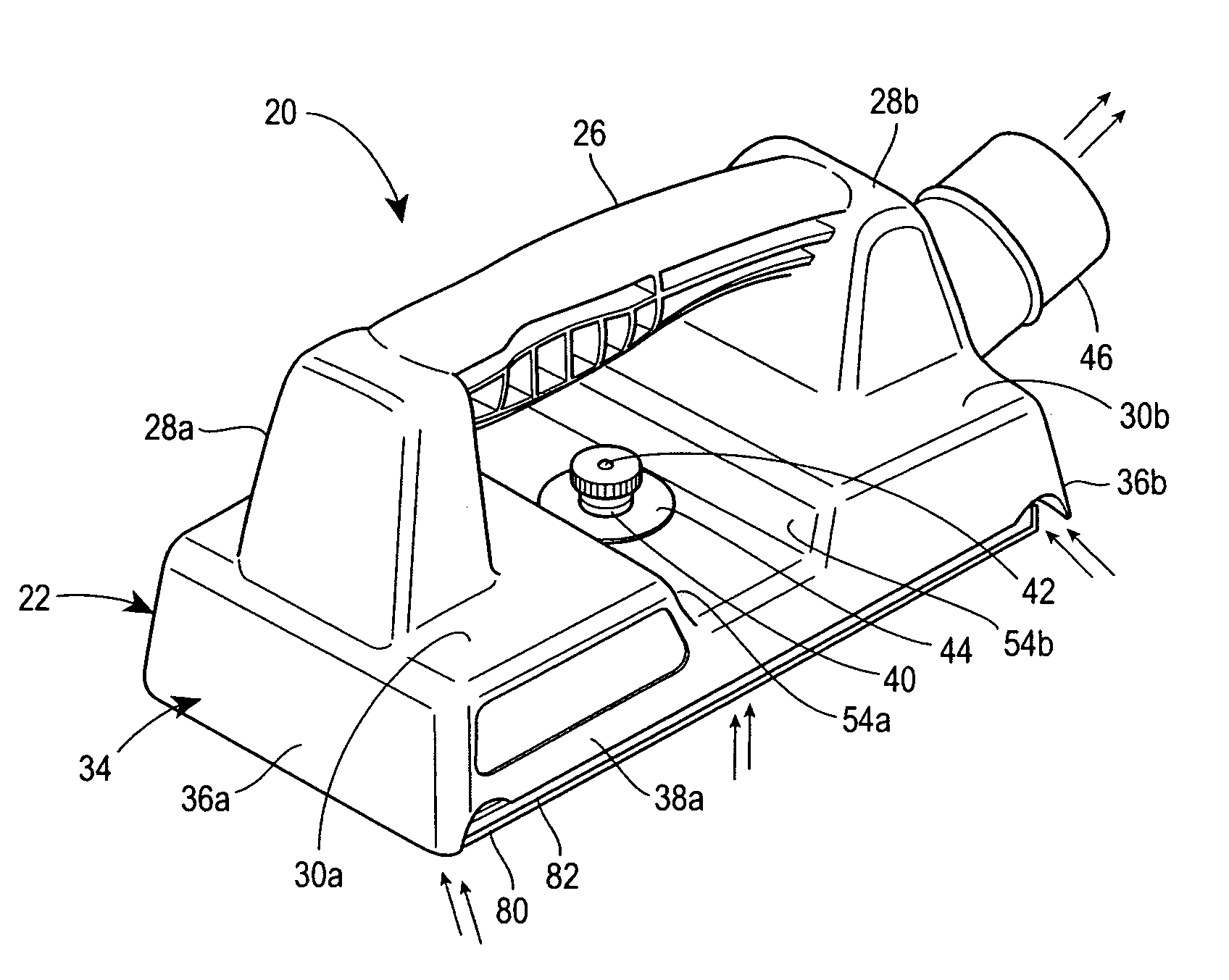
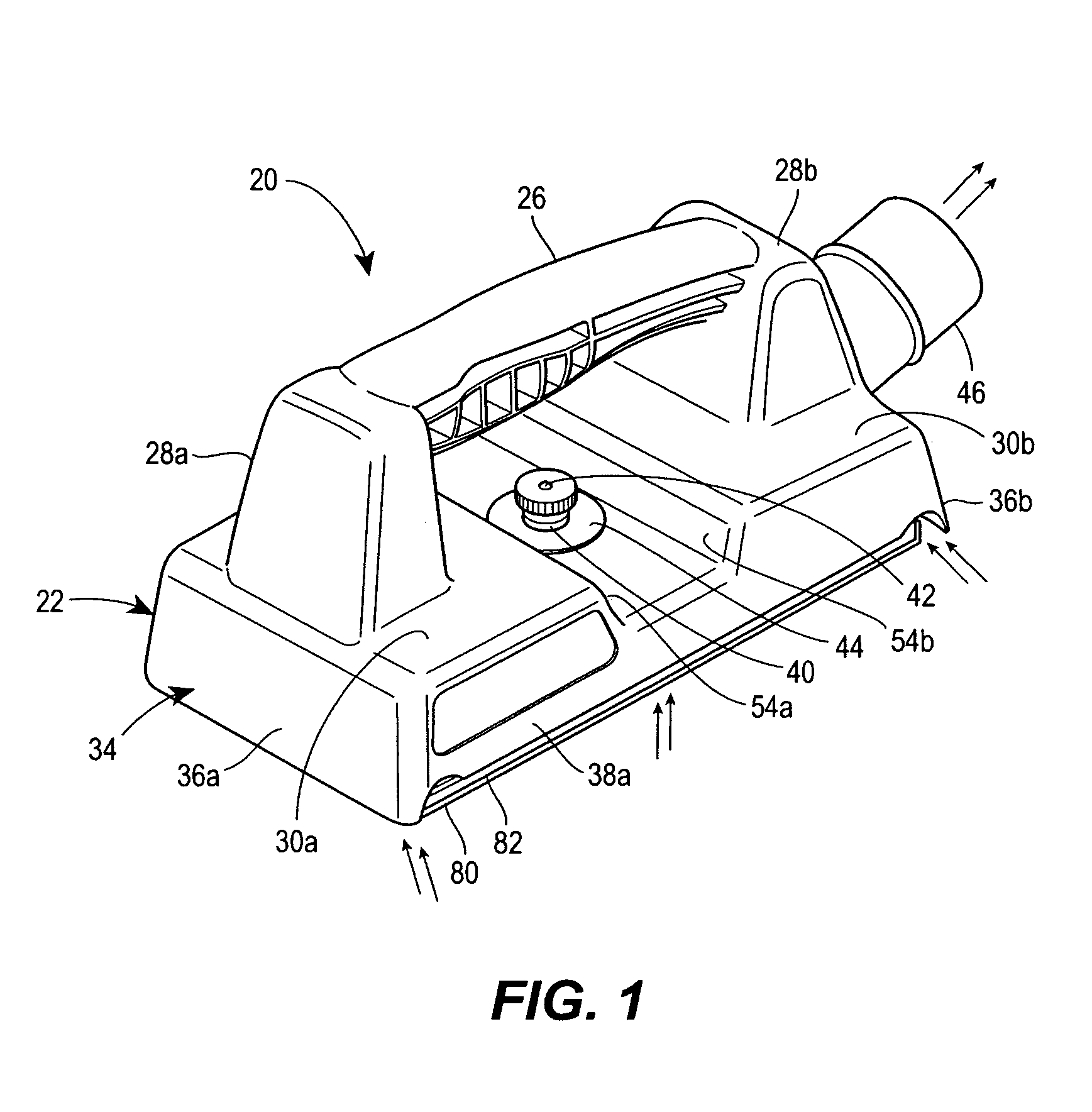
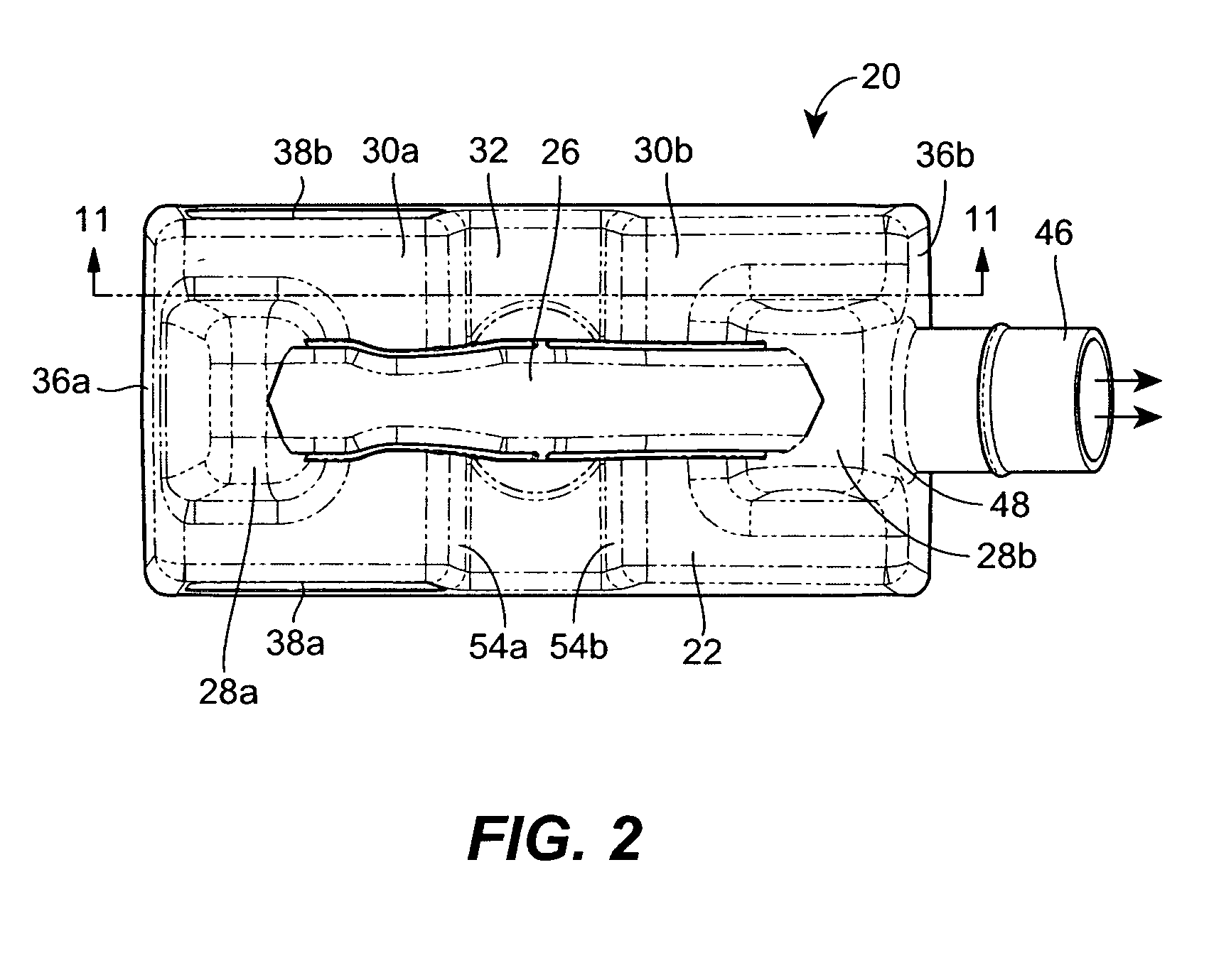
[0019]With reference to the drawings, in which like reference numerals indicate like elements, there is shown in FIG. 1 the hand sander vacuum attachment assembly of the present disclosure, generally denoted by reference numeral 20. Assembly 20 is preferably formed primarily of injection-molded plastic components, comprising an upper body housing portion 22 and a lower sanding backer plate portion 24, which when assembled together create the overall vacuum sander assembly 20. The housing portion 22 includes a handle segment 26 formed and supported between two upstanding generally hollow support stanchions 28a, 28b, the latter being respectively formed integral with front and rear platform sections 30a, 30b, which in turn are separated by a central trough portion 32. Further, the handle 26 is preferably formed as a solid component, such that there is no vacuum air flow through the same, which thereby assists in helping maintain the substantial majority of the vacuum air flow under th...


PUM


Abstract

A manual sander vacuum attachment, providing edge sanding and multiple positioning capabilities, having a lower sanding backer plate member, which carries a soft sanding pad and secures the sandpaper sheet, and an upper housing portion, having a generally horizontal platform with two vertically-extending stanchion supporting a handle therebetween, with a vacuum fitting for connection to a hose for a vacuum air source, and a peripheral skirt surrounding the backer plate member, whereby all vacuum air flow of sanded debris travels about periphery of sander backing plate up into interior of the housing portion.

Description

FIELD OF THE DISCLOSURE[0001]This disclosure relates to a hand-operated sanding tool for attachment to a vacuum source, and more particularly to such an apparatus having edge-sanding and multiple positioning capabilities.BACKGROUND OF THE DISCLOSURE[0002]There have been numerous attempts to provide hand sanding tools, blocks and other apparatus that will connect, via a vacuum hose, to a vacuum source. Many of such known sanding tools have no capability of adjustment, such that the sanding tool cannot be used for close-in edge-sanding purposes. Further, for many of the prior known vacuum-type sanding tools, the airflow created by the vacuum goes directly through the sanding pad or directly through the sandpaper, or both, thereby mandating the use of an open, flow-through type of sanding screen. This greatly limits the user's options as to availability of sanding medium. Furthermore, these types of screens may be subject to plugging due to build up of debris or other variables. This p...

Claims


Application Information

Patent Timeline
IPC IPC(8): B24B15/04B24B55/10
CPCB24D15/023B24B55/10
Inventor SEASHOLTZ, CRAIG A.BUSS, RANDY L.KEPNER, MATTHEW S.
Owner SHOP VAC
Why Eureka
Try Eureka