
High-efficiency dust collecting device with two gateways

a dust collection device and high-efficiency technology, applied in the field of sand grinders, can solve the problems of large power collectors, increase costs, inconvenience in assembly or operation, etc., and achieve the effects of reducing costs, facilitating installation, and prolonging the service life of sanding belt rollers

Inactive Publication Date: 2008-08-21
CHUANG PO CHANG
View PDF12 Cites 26 Cited by
  • Summary
  • Abstract
  • Description
  • Claims
  • Application Information

AI Technical Summary

Benefits of technology

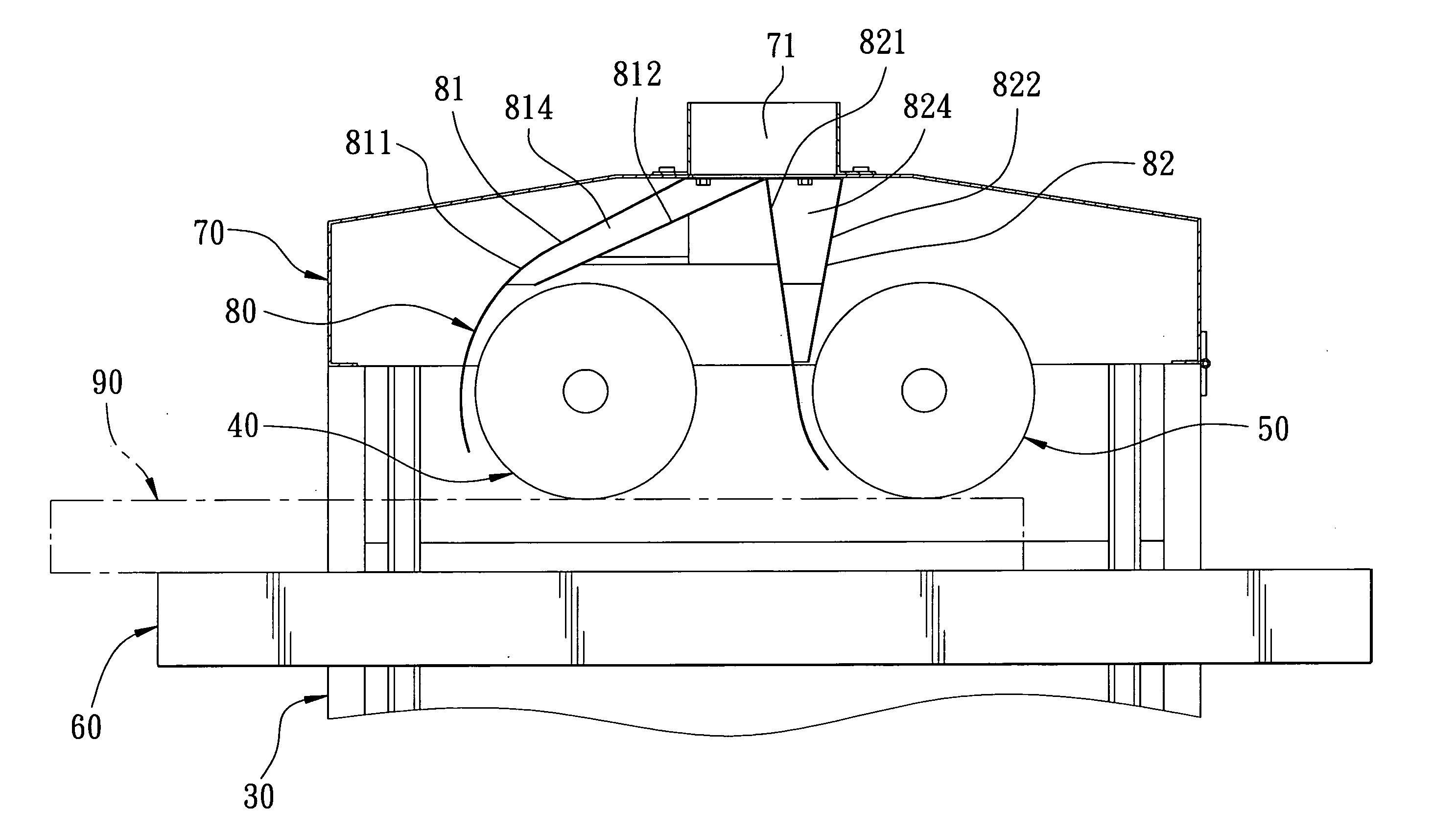
[0006]The main characteristics of the invention are a first gateway set and a second gateway set, which are both formed integrally with a metallic panel. The dust-collecting device is connected with exits of a cover of the sand grinder and above two sanding belt rollers. Each of the gateway sets is provided with an arc-like panel, a blocking plate, and two dust-guiding plates. A gateway is formed between the arc-like panel and the blocking plate so as to suck in the dust or the wood flour generated while grinding a workpiece. The dust or the wood flour is then sucked further to pass through the exits to the collecting device, favored by the dust-guiding plates. The collecting position of the dust collecting device is raised high enough so that the device can effectively collect the dust via help of the dust-guiding plates shaped oblique, keeping the sanding belt rollers free from dust, advancing the processed precision of the workpiece, prolonging the service life of the sanding belt rollers and needing only a relatively small power motor for a reduction of cost. Moreover, the dust-collecting device is formed integrally by a metallic panel, it is easy to be installed under the cover, providing a simple assembly and a low cost.

Problems solved by technology

Suppose a better sucking is to be achieved, a larger power collector is the only solution, relatively increasing cost.
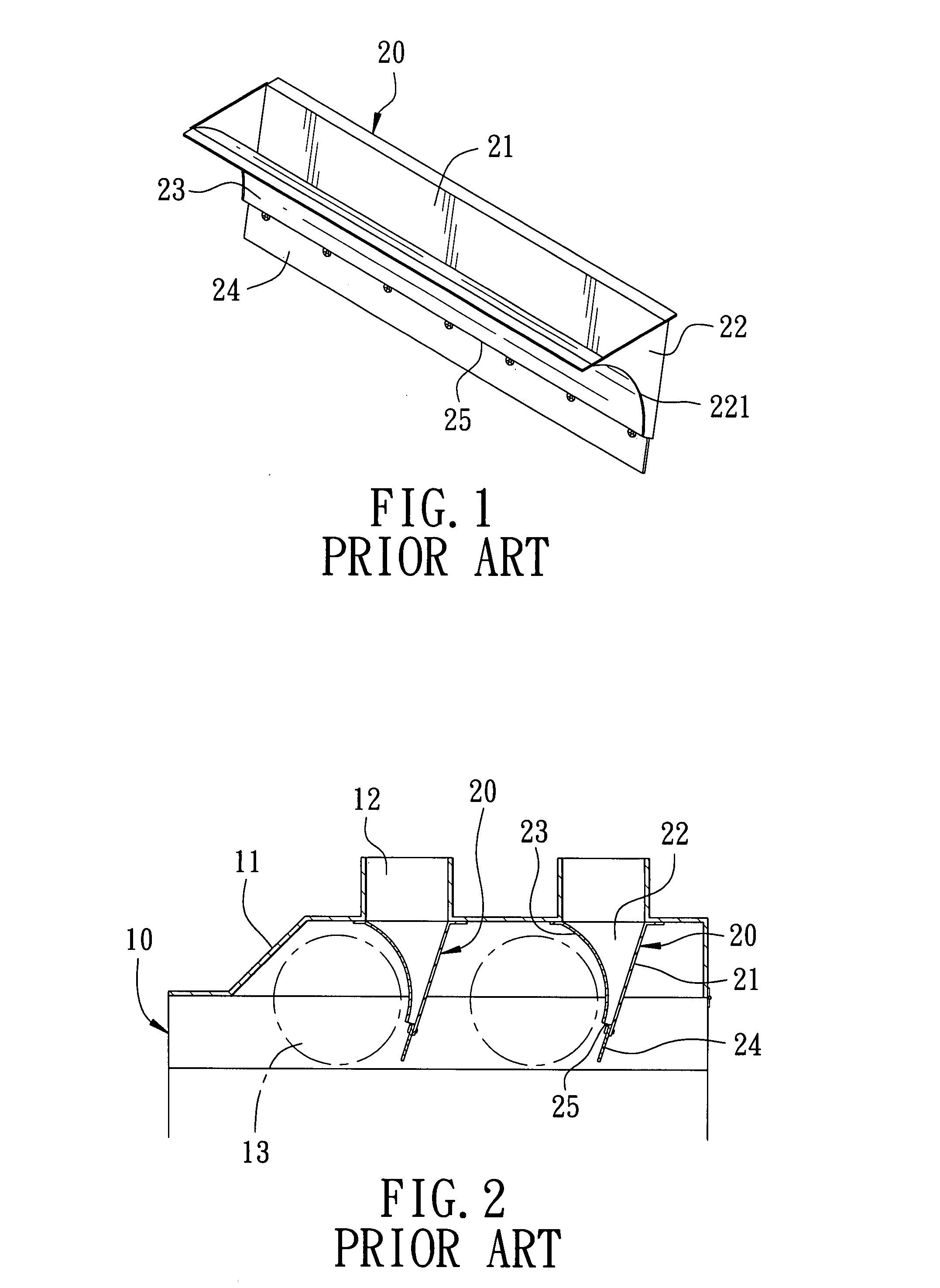
Moreover, the assembly of the dust collector 20 is complicated and each roller 13 needs a set of the dust collector 20, causing an inconvenience for assembly or operation.

Method used


Image

  • High-efficiency dust collecting device with two gateways
  • High-efficiency dust collecting device with two gateways
  • High-efficiency dust collecting device with two gateways

Examples


Embodiment Construction

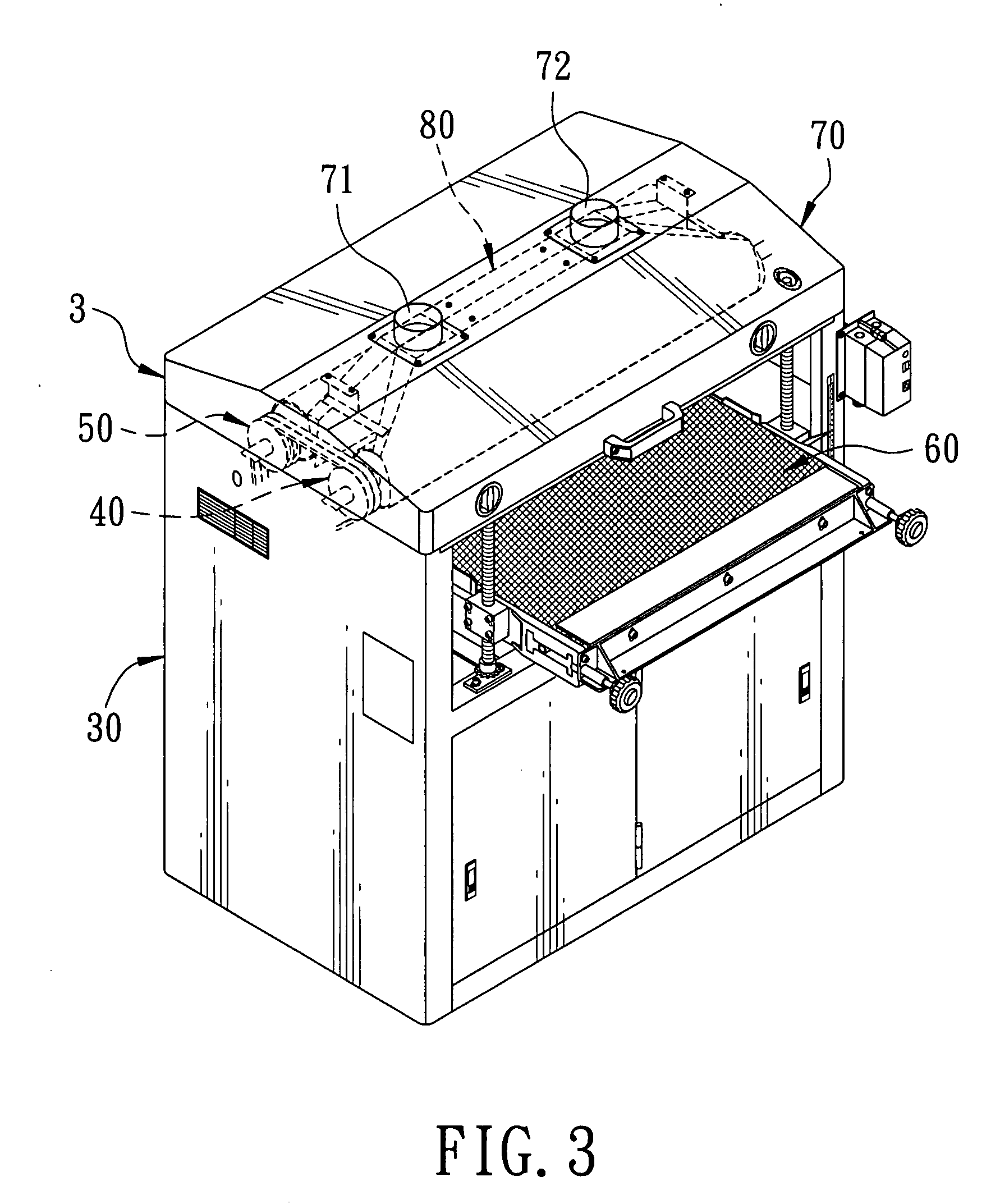
[0015]FIGS. 3˜5 show a preferred embodiment of a high-efficiency dust collecting device with two gateways for a sand grinder 3 in the present invention. The sand grinder 3 is composed of a main body 30, a front sanding belt roller 40 and a rear sanding belt roller 50 located transversely on the top of the main body 30, a conveying table 60 located under the two sanding belt rollers 40 and 50, and a cover 70. So, a workpiece is to be put on the conveying table 60 and ground below and by the front sanding belt roller 40 and the second sanding belt roller 50 in order. The cover 70 is transversely cut with two exits 71 and 72 on its top, connected with a dust collecting device 80 installed under it at one side of each of the front sanding belt roller 40 and the second sanding belt roller 50. The dust-collecting device 80 is connected with the exits 71 and 72, provided with a first gateway set 81 and a second gateway set 82.

[0016]The first gateway set 81 is formed integrally with a metal...


PUM


Abstract

A high-efficiency dust collecting device with two gateways is connected with exits of a cover of a sand grinder and above two sanding belt rollers., composed of a first gateway set and a second gateway set, which are both formed integrally with a metallic panel and provided respectively with a first and a second arc-like panel, a first and a second blocking plate, and two first and two second dust-guiding plates. A first and a second gateway are respectively formed between the arc-like panel and the blocking plate so as to suck in the dust or the wood flour generated while grinding a workpiece. The dust or the wood flour is then sucked further to pass through the exits to the collecting device, favored by the dust-guiding plates.

Description

BACKGROUND OF THE INVENTION[0001]1. Field of the invention[0002]This invention relates to a sand grinder, particularly to one installed with a high-efficiency dust-collecting device with two gateways, able to effectively collect dust or wood flour generated while grinding a wood workpiece.[0003]2. Description of the Prior Art[0004]Commonly, as shown in FIGS. 1 and 2, a conventional dust collector 20 is installed between an exit 12 set above a cover 11 of a sand grinder 10 and one side of a roller 13. The dust collector 20 is provided with a blocking plate 21, two side plates 22, a dust blocker 23 and a flexible extender 24. The side plates 22 formed triangular are fixed at two sides of the blocking plate 21, respectively provided with an arc-like edge 221 formed in its one side for fixing with the dust blocker 23, so that a sucking mouth 25 is formed between the dust blocker 23 and the blocking plate 21 to suck powder dust or wood flour made by the roller 13 through the exit 12 to a...

Claims


Application Information

Patent Timeline
IPC IPC(8): B24B55/06
CPCB24B55/06
Inventor CHUANG, PO CHANG
Owner CHUANG PO CHANG
Learn More