Nanoscale high-flow pin-type sand mill

A large flow, pin-type technology, applied in grain processing, etc., can solve the problems that the central part of the grinding cylinder cannot be effectively cooled, the rotation speed of the rotating shaft is limited, and the effect is not ideal, so as to improve the grinding efficiency, increase the rotation speed, The effect of high pass rate

Active Publication Date: 2010-06-30
PUHLER GUANGDONG SMART NANO TECH CO LTD
View PDF1 Cites 29 Cited by
  • Summary
  • Abstract
  • Description
  • Claims
  • Application Information

AI Technical Summary

Problems solved by technology

At present, the method used is usually to install a cooling water jacket in the grinding cylinder, but the effect is not ideal, the cooling is not obvious, and the central part of the grinding cylinder cannot be effectively cooled, which further limits the improvement of the rotation speed of the rotating shaft

Method used


Image

  • Nanoscale high-flow pin-type sand mill
  • Nanoscale high-flow pin-type sand mill
  • Nanoscale high-flow pin-type sand mill

Examples


Embodiment Construction

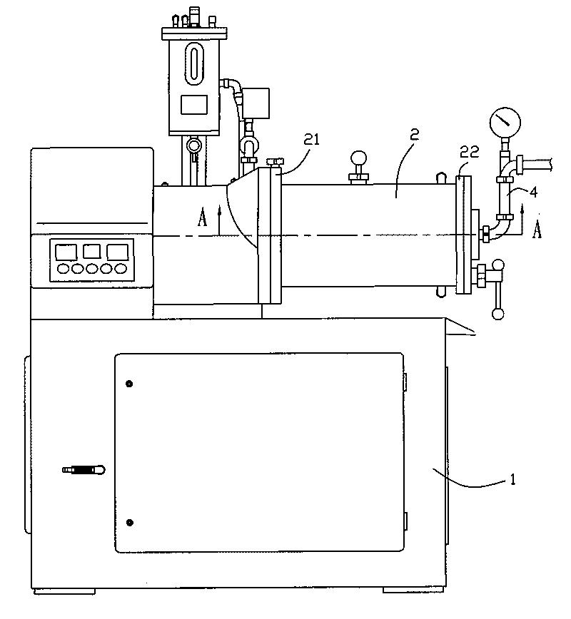
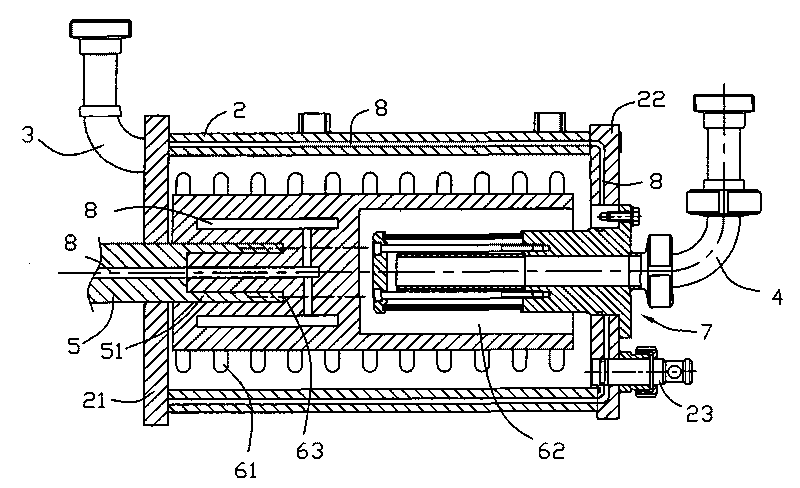
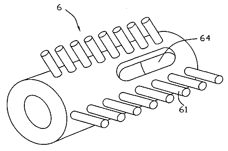
[0017] see Figure 1 to Figure 3 , shows a preferred mode of the nano-scale large-flow pin-pin sand mill of the present invention, including a frame 1 and a grinding cylinder 2 sealed by left and right end covers 21, 22 arranged on the frame, and a rotating shaft 5 passes through The left end cover 21 extends into the grinding cylinder, a rotor 6 is fixed on the rotating shaft 5, and several rows of rod pins 61 are installed on the peripheral wall of the rotor in the axial direction. The material enters the grinding cylinder 2 from the feed pipe 3 at the left end of the grinding cylinder. Under the action of the rotation of the rod pin 61 on the rotor, the material in the grinding cylinder and the grinding medium continuously collide and generate centrifugal force, so that the material is fully dispersed and ground. Then, the principle of dynamic centrifugal separation is used to make the ground material flow out from the discharge pipe 4 through the separator 7 . One end of ...


PUM


Abstract

The invention relates to a nanoscale high-flow pin-type sand mill comprising a rack and a sand cylinder which is arranged on the rack and is sealed by a left cover and a right cover, wherein a feed pipe and a discharging pipe are respectively arranged on the two sides of the sand cylinder; a spindle passes through the left end cover to extend into the sand cylinder and is fixedly provided with a rotor; the surrounding wall of the rotor is axially provided with a plurality of rows of pins; a separator is installed on the sand cylinder and is communicated with the discharging pipe; one end of the rotor is installed on the spindle, and the other end of the rotor is axially provided with a groove; one end of the separator is fixed on the right end cover; and the other end of the separator passes through the right end cover to extend into the groove. In this way, the length of the sand cylinder can be effectively shortened to increase the diameter thereof, thus the spindle can be designed to be short and thick so as to improve the rotational speed of the spindle and increase the linear speed of the material and grinding medium in the sand cylinder; and the material is fully dispersed and ground to ensure grinding precision and improve grinding efficiency.

Description

technical field [0001] The invention relates to a horizontal sand mill, in particular to a nanoscale large-flow pin-pin sand mill. Background technique [0002] On the basis of ensuring the grinding accuracy, improving the grinding efficiency is the research direction of the sand mill. Existing rod-pin sand mills include a frame and a grinding cylinder arranged on the frame and sealed by left and right end covers. A rotating shaft is arranged in the grinding cylinder, and a rod pin is directly installed on the rotating shaft, or a rotor is installed on the rotating shaft. Then on the rotor rod pins are installed again, and the separating device is generally installed on the end of the rotating shaft or on one side of the rotor, as in Chinese patent (200520032444.X). This structure determines that the length design of the grinding cylinder of the sand mill should be longer, so the length of the rotating shaft needs to be very long, which limits the increase in the rotational...

Claims


Application Information

Patent Timeline
Patent Type & Authority Applications(China)
IPC IPC(8): B02C17/16B02C17/18
Inventor 雷立猛
Owner PUHLER GUANGDONG SMART NANO TECH CO LTD
Why Eureka
Try Eureka