Stent delivery device

a technology of stent and stent insertion, which is applied in the field of catheter-based systems, can solve the problems of improper placement and unwanted movement of the deployed device, difficult to remember which direction, and inability to provide very precise control of the retraction of the sheath

Inactive Publication Date: 2006-04-25
ENDOTEX INTERVENTIONAL SYST
View PDF13 Cites 46 Cited by
  • Summary
  • Abstract
  • Description
  • Claims
  • Application Information

AI Technical Summary

Problems solved by technology

This, however, may not provide very precise control of the retraction of the sheath.
With such devices, however, it may be difficult to remember which direction, i.e., clockwise or counterclockwise, is appropriate either to retract or advance the sheath with respect to the catheter.
This distal movement may result in the improper placement and unwanted movement of the deployed device.
This distal movement of the sheath is particularly problematic in the deployment of stents or other tubular prostheses.
Another disadvantage in current screw-type devices is that the devices are often complicated, including many parts which may be difficult to assemble and / or expensive to make.

Method used


Image

  • Stent delivery device
  • Stent delivery device
  • Stent delivery device

Examples


Embodiment Construction

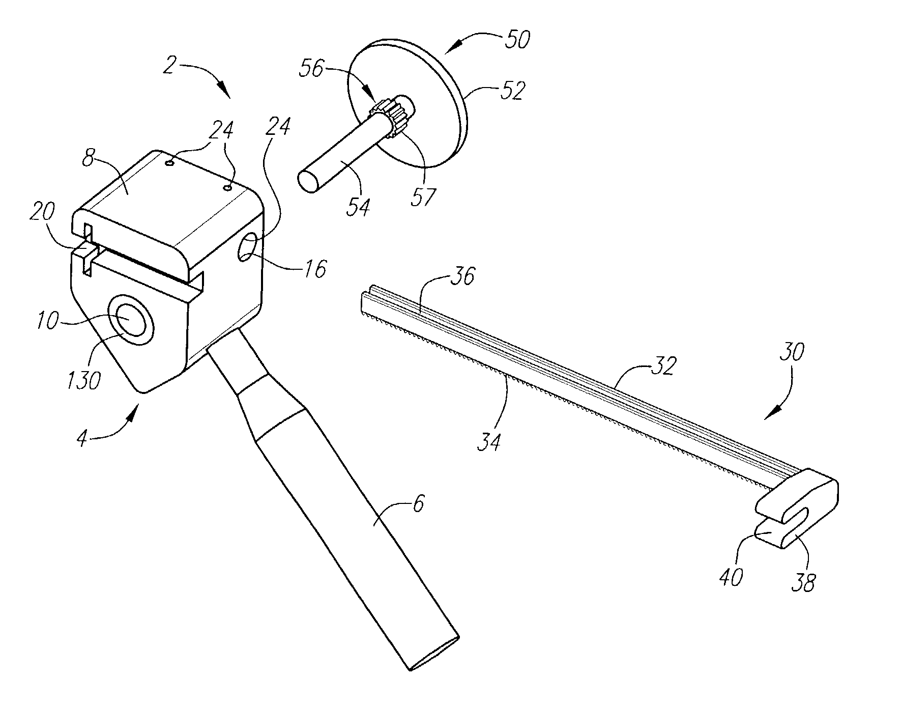
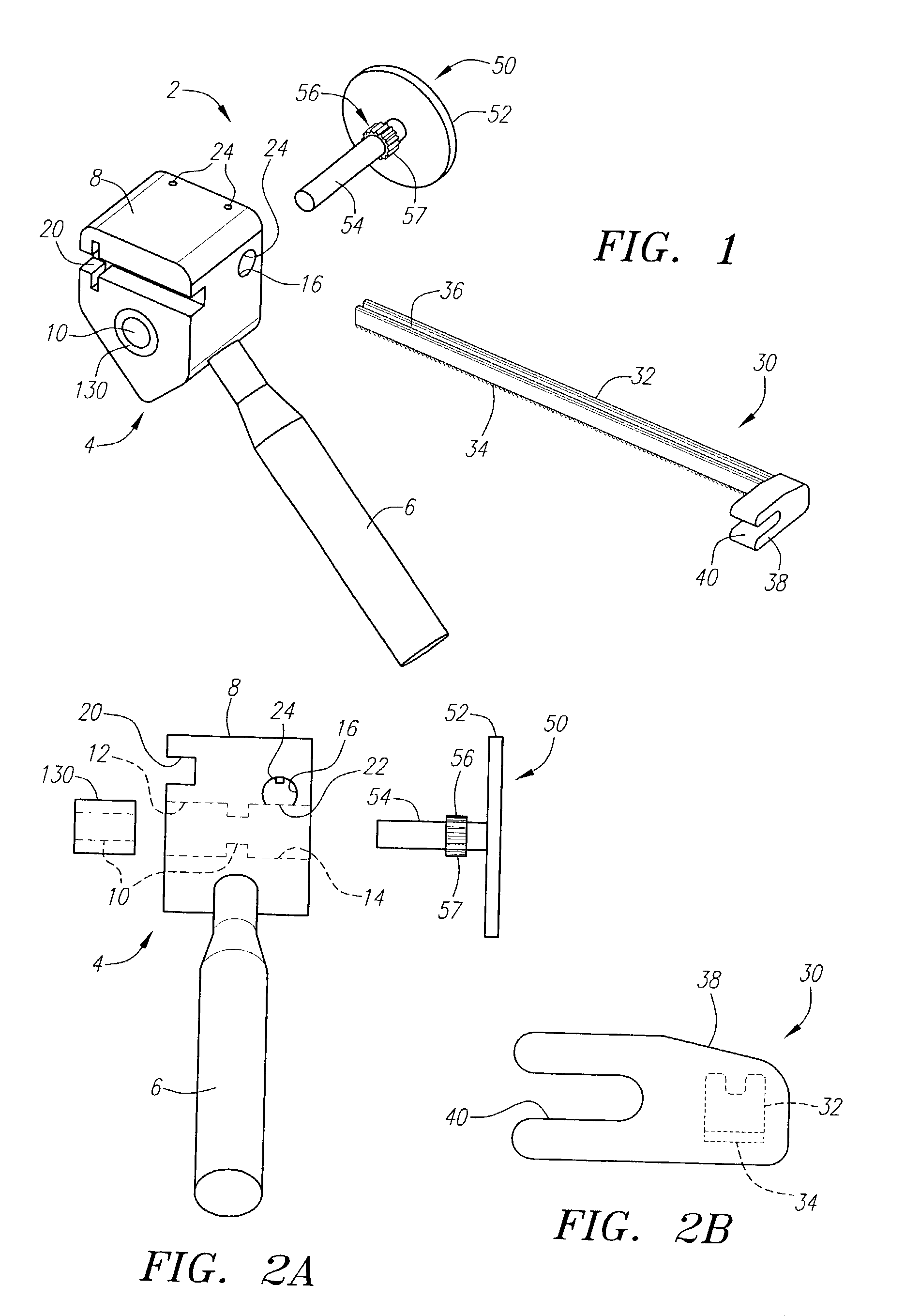
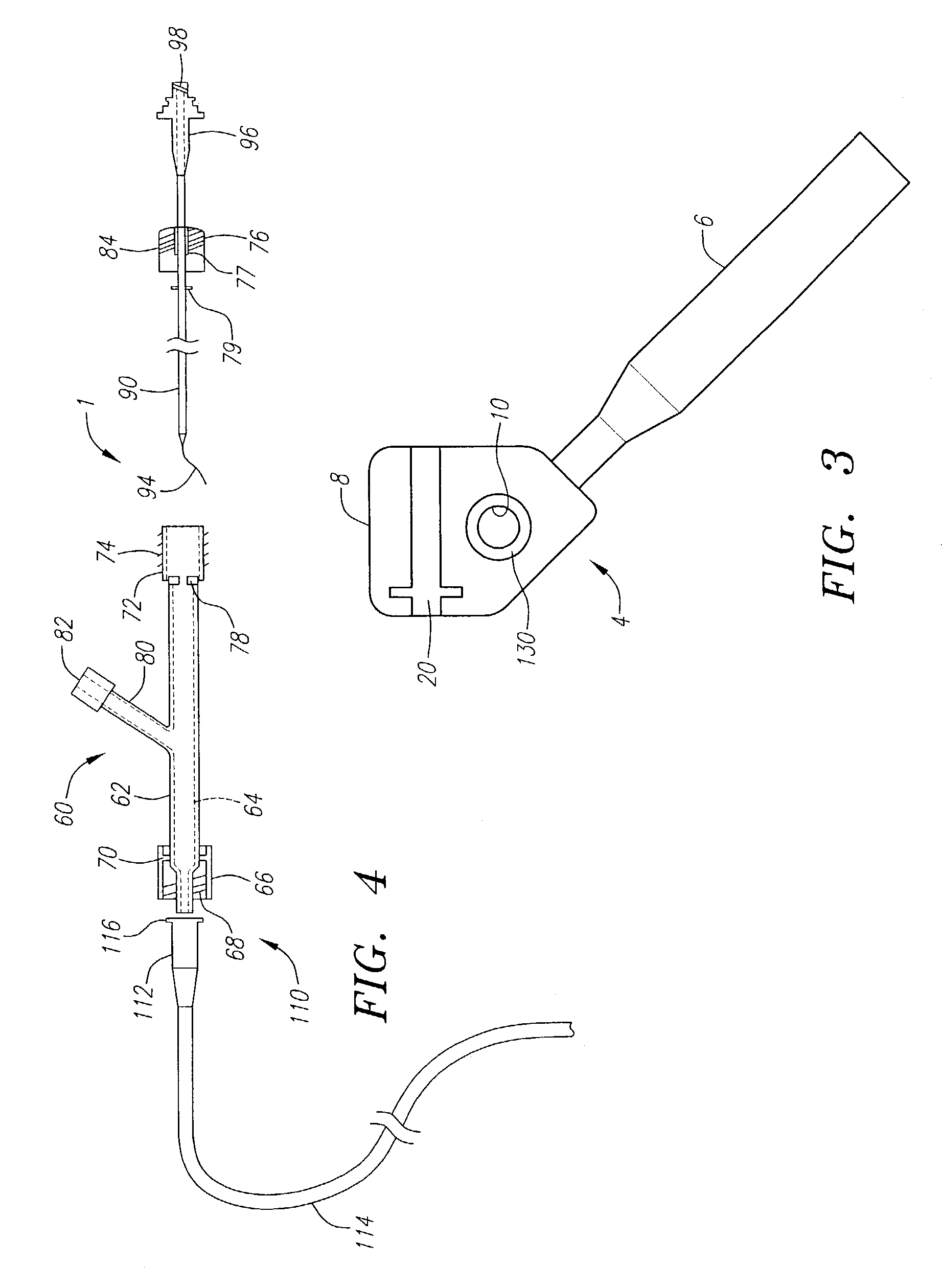
[0025]Turning now in detail to the drawings, FIGS. 1, 3, and 4 show a handle device 2 in accordance with the invention that may include as few as three parts, namely, a handle member 4, a shaft 54, and needle bearing clutch 130.

[0026]In one preferred embodiment of the invention, the handle device 2 includes a handle member 4, a control knob 50, and a control member 30. The handle member 4, control knob 50, and control member 30 can be made of materials such as molded or machined plastic, or stainless steel. Any material commonly used within the medical device field can be used in the handle device 2.

[0027]Turning in more detail to the handle member 4, the handle member 4 preferably comprises a grip portion 6 and a body portion 8. The grip portion 6 is generally tubular in shape and projects from the body portion 8 at an oblique angle. In use, the grip portion 6 preferably extends in a forward or distal direction away from the user.

[0028]Referring to FIGS. 1, 2, and 3, the body porti...


PUM


Abstract

A unidirectional handle device for an endoluminal device includes an outer tubular member and an elongate inner member slidably received in the outer tubular member. The unidirectional handle includes a handle member, a needle bearing clutch disposed in the handle member, a control member guide, and shaft rotatable in a single direction disposed within the handle member. The shaft is rotatable in a single direction by its engagement with the needle bearing clutch. The shaft is in rotational engagement with the outer tubular member of the endoluminal device. The outer tubular member is slidable from a distal position to a proximal position when the shaft is rotated in the single direction. The unidirectional handle device provides substantially no backlash of the outer tubular member. In addition, the unidirectional handle device advantageously produces a tension-retaining effect during use.

Description

RELATED INFORMATION[0001]This application is a continuation of application Ser. No. 09 / 613,872, now U.S. Pat. No. 6,527,779, the disclosure of which is expressly incorporated herein by reference.FIELD OF THE INVENTION[0002]The present invention relates generally to catheter-based systems for treating a remote location within a patient, and more particularly to handles for stent delivery systems, electrophysiology devices and the like, which include a catheter and a retractable sheath thereon.BACKGROUND OF THE INVENTION[0003]Devices having a retractable sheath associated with a catheter are used to treat a variety of conditions using endoluminal methods instead of open surgical procedures. For example, angioplasty and stent implantation procedures are often used to treat atherosclerotic disease or other occlusive conditions in blood vessels, such as the coronary and carotid arteries. During angioplasty, for example, a catheter having an uninflated balloon on its distal end is percuta...

Claims


Application Information

Patent Timeline
Patent Type & Authority Patents(United States)
IPC IPC(8): A61F11/00A61F2/82A61F2/06A61F2/84
CPCA61F2/95A61F2002/9517A61F2/9517
Inventor ROURKE, JONATHAN M.
Owner ENDOTEX INTERVENTIONAL SYST
Why Eureka
Try Eureka