Suture lock having non-through bore capture zone

a technology of suture lock and capture zone, which is applied in the field of suture lock, can solve the problems of increased closure time, difficulty in proper knot tying, and limited access to the surgical site, and achieve the effect of being easily adjusted

Inactive Publication Date: 2006-04-25
INCISIVE SURGICAL
View PDF40 Cites 375 Cited by
  • Summary
  • Abstract
  • Description
  • Claims
  • Application Information

AI Technical Summary

Benefits of technology

[0011]The suture lock of the present invention overcomes the limitations of the prior art. The locking mechanism of the suture lock provides enough strength so that fenestration of the suture through a suture lock bore is not required. In addition, the suture lock is designed for use with an applicator that allows the placement of multiple fasteners without withdrawing and reloading the applicator. Finally, the suture lock can be readily adjusted, either through disengagement of the mating elements or through application of a frictionally directing surface on the mating element, which provides the physician ample opportunity to cinch, tighten, or otherwise adjust the tension of the suture lock.

Problems solved by technology

Depending on the location, access to the surgical site may be limited creating difficulties with proper knot tying.
These difficulties can lead to ineffective suture closure as well as increased closure times. Ultimately, these difficulties lead to increased surgical risks to the patient as well as adverse economic effects derived from longer closure times.
While these mechanical gripping devices have improved the speed and reliability of internal sutures, there remain considerable drawbacks.
Depending on the suture location, threading through this fenestration may be nearly as difficult and time consuming as tying a knot.
Many of the devices have closure mechanisms that make it nearly impossible to design applicators capable of reloading and applying additional fasteners without withdrawing the applicator from the suture site.
In addition, many of the applicators have little or no adjustment capacity once the closure device is applied should a physician need to further cinch and / or adjust the suture tension.

Method used


Image

  • Suture lock having non-through bore capture zone
  • Suture lock having non-through bore capture zone
  • Suture lock having non-through bore capture zone

Examples


Embodiment Construction

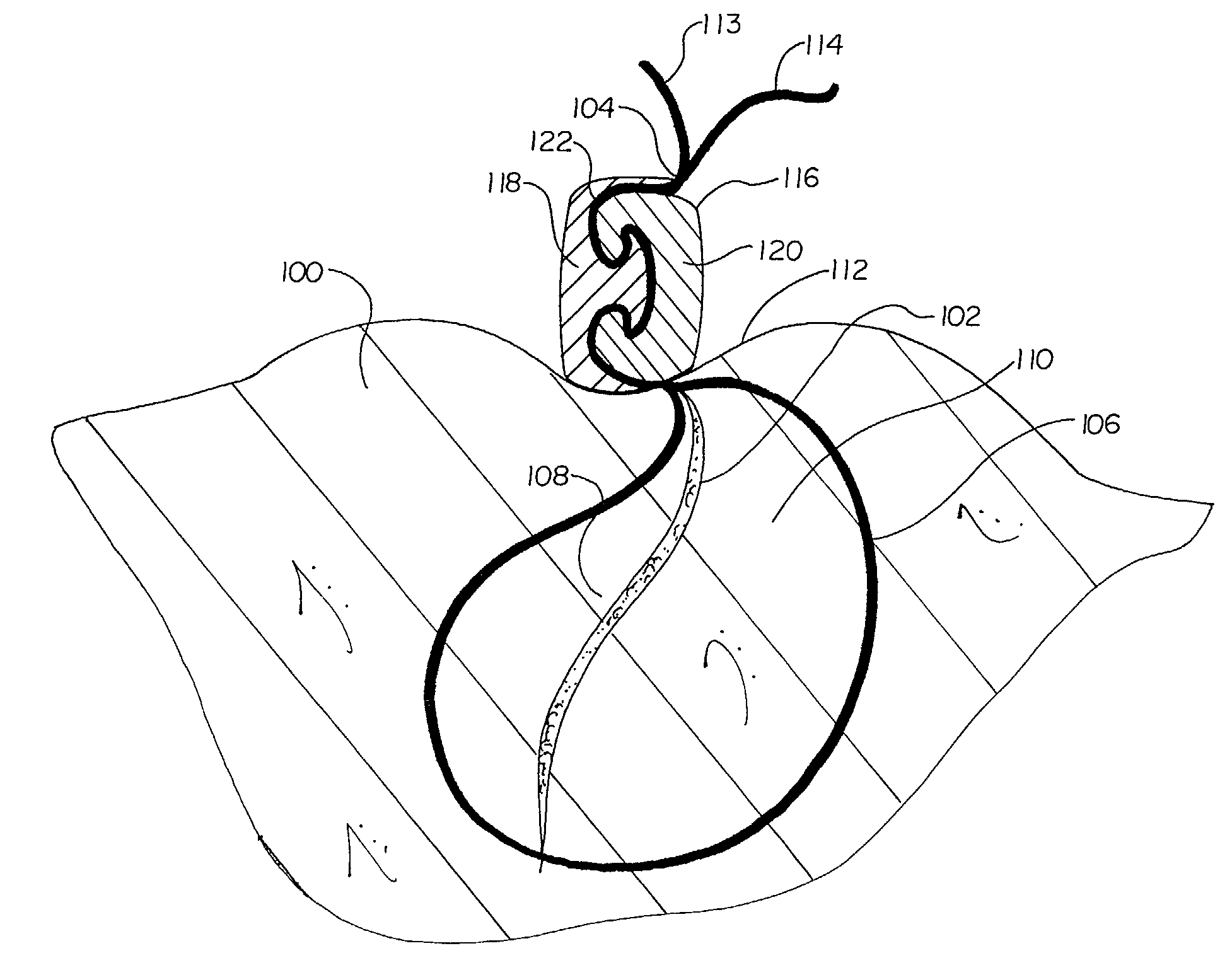
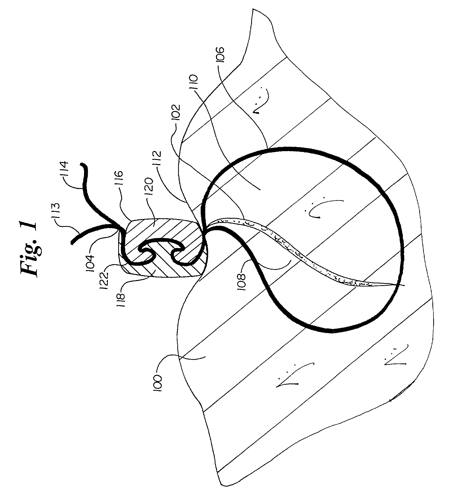
[0027]FIG. 1 depicts a tissue closure using the suture lock of the present invention. Tissue 100 is separated by a tissue opening or incision 102. Using a length of suture 104, a physician draws together living tissue 100 through the use of a suture loop 106. Suture loop 106 forcibly draws opposing layers 108 and 110 of living tissue 100 into intimate physical contact. Suture 104 exits the tissue 100 at a tissue surface 112. Where suture 104 exits the tissue surface 112, a pair of suture ends or segments 113 and 114 are present. Suture 104 is held in place at the tissue surface 112 through the use of a suture lock 116, as will be described.

[0028]For purposes of the present invention, it will be understood that suture lock 116 can be used to secure suture segments 113 and 114 in a variety of configurations. While suture 104 is typically used to close an opening, wound, or incision 102, it will be recognized that suture lock 116 may be used with sutures 104 for other purposes, such as...


PUM


Abstract

A suture lock utilizes a first engaging element and a second engaging element to define a non-through bore capture zone. Each of the engaging elements possesses a surface including at least one mating element that corresponds to a mating element on a surface of the opposing engaging element. When engaged across suture segments, the mating elements apply a frictional holding force to the suture segments. The frictional holding force secures the suture along the length of the suture in the capture zone between the mating elements.

Description

CLAIM TO PRIORITY[0001]This application claims benefit of U.S. Provisional Application No. 60 / 296,796 filed Jun. 8, 2001, entitled, “SUTURE CLIP,” which is incorporated herein by reference.FIELD OF THE INVENTION[0002]The present invention relates generally to a tissue closure apparatus and methods. More particularly, the present invention relates to a suture lock having first and second engaging elements that create a non-through bore capture zone that frictionally secures a suture when the engaging elements are mated.BACKGROUND OF THE INVENTION[0003]When an opening in tissue is created either through an intentional incision or an accidental wound or laceration, biological healing of the opening commences through the proximity of living tissue. If the opening is very large or if its location subjects the wound to continual movement, a physician will seek to forcibly hold the sides of the incision or wound in close proximity so as to promote the healing process. The most prevalent me...

Claims


Application Information

Patent Timeline
Patent Type & Authority Patents(United States)
IPC IPC(8): A61B17/04
CPCA61B17/0487A61B2017/0488A61B2017/0464A61B2017/0454
Inventor PETERSON, JAMES
Owner INCISIVE SURGICAL
Why Eureka
Try Eureka