

Lens system
- Summary
- Abstract
- Description
- Claims
- Application Information
AI Technical Summary
Benefits of technology
Problems solved by technology
Method used
Image

Examples
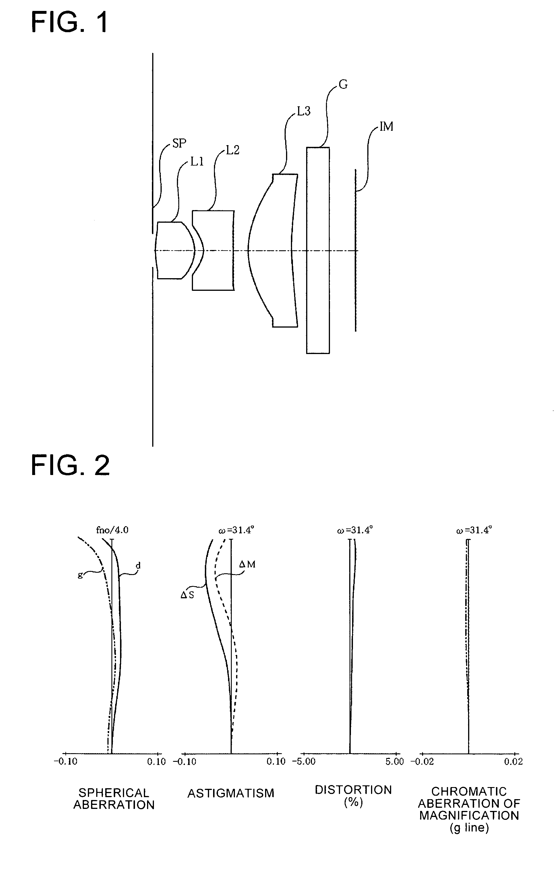
numerical example 1
[0132]
f = 4.500Fno = 4.002ω = 70.8°R1 = stopD1 = 0.05R2 = 3.347D2 = 1.30N1 = 1.609700ν1 = 57.8R3 = −1.082D3 = 0.29R4 = −0.781D4 = 1.00N2 = 1.814740ν2 = 37.0R5 = −7.082D5 = 0.47R6 = 1.960D6 = 1.45N3 = 1.609700ν3 = 57.8R7 = 8.103D7 = 0.50R8 = ∞D8 = 0.75N4 = 1.516330ν4 = 64.1R9 = ∞
Aspheric coefficients
Surface 2[0133]k=6.16735e+00[0134]B=−8.58545e−02 C=1.98508e−02 D=3.31078e−01 E=3.14242e−01
Surface 3[0135]k=−4.37113e+00[0136]B=−2.52227e−01 C=2.43272e−01 D=−2.90238e−01 E=1.30428e−01
Surface 4[0137]k=−2.72888e+00[0138]B=−7.80081e−02 C=1.52160e−01 D=−2.15722e−01 E=1.29902e−01
Surface 5[0139]k=−4.93025e+01[0140]B=2.29842e−02 C=2.04252e−02 D=−1.03655e−02 E=2.11986e−03
Surface 6[0141]k=−6.61590e+00[0142]B=4.04050e−03 C=−1.22536e−04 D=4.54480e−05 E=−3.78066e−06
Surface 7[0143]k=−6.07398e+01[0144]B=0.00000e+00 C=0.00000e+00 D=0.00000e+00 E=0.00000e+00
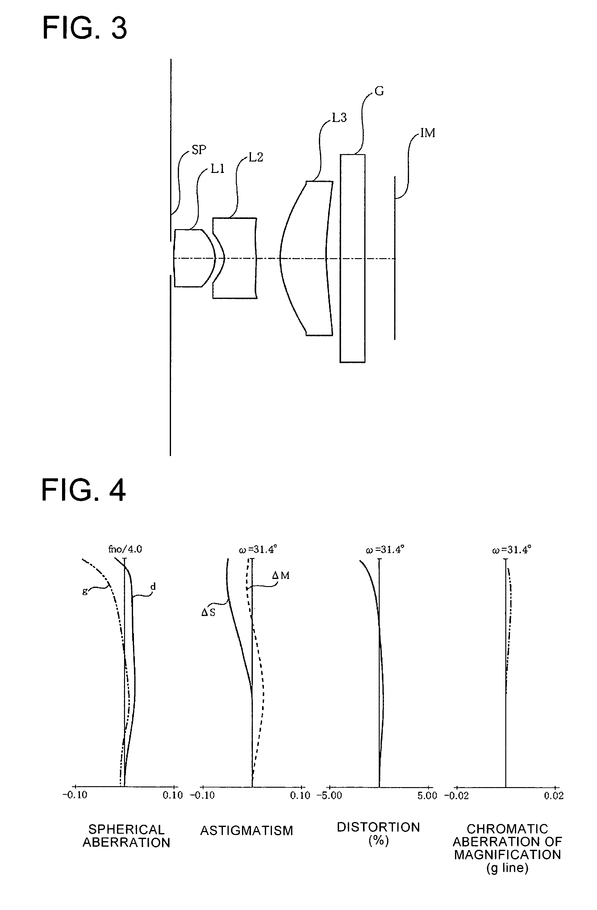
numerical example 2
[0145]
f = 4.500Fno = 4.002ω = 70.8°R1 = stopD1 = 0.05R2 = 4.378D2 = 1.30N1 = 1.714300ν1 = 38.9R3 = −1.276D3 = 0.29R4 = −0.797D4 = 1.00N2 = 1.839170ν2 = 23.9R5 = −3.413D5 = 0.70R6 = 3.086D6 = 1.45N3 = 1.693840ν3 = 53.1R7 = 9.047D7 = 0.50R8 = ∞D8 = 0.75N4 = 1.516330ν4 = 64.1R9 = ∞
Aspheric Coefficients
Surface 2[0146]k=1.19204e+01[0147]B=−7.99231e−02 C=3.48264e−02 D=−3.97640e−01 E=4.25675e−01
Surface 3[0148]k=−5.30315e+00[0149]B=−2.66192e−01 C=2.37700e−01 D=−2.17984e−01 E=7.83461e−02
Surface 4[0150]k=−2.27857e+00[0151]B=−6.67579e−02 C=1.75921e−01 D=−1.95240e−01 E=9.34029e−02
Surface 5[0152]k=−1.97347e+01[0153]B=2.47475e−02 C=2.91784e−02 D=−1.40981e−02 E=2.53952e−03
Surface 6[0154]k=−6.04971e+00[0155]B=3.13146e−03 C=−1.10723e−04 D=5.84522e−05 E=−4.99909e−06
Surface 7[0156]k=−1.99347e+01[0157]B=0.00000e+00 C=0.00000e+00 D=0.00000e+00 E=0.00000e+00
numerical example 3
[0158]
f = 4.500Fno = 4.002ω = 70.8°R1 = stopD1 = 0.05R2 = 4.378D2 = 1.30N1 = 1.632460ν1 = 63.8R3 = −1.306D3 = 0.41R4 = −0.868D4 = 1.00N2 = 1.810000ν2 = 41.0R5 = −2.928D5 = 0.70R6 = 4.158D6 = 1.45N3 = 1.632460ν3 = 63.8R7 = 14.493D7 = 0.50R8 = ∞D8 = 0.75N4 = 1.516330ν4 = 64.1R9 = ∞
Aspheric Coefficients
Surface 2[0159]k=1.19116e+01[0160]B=−8.03371e−02 C=3.48264e−02 D=−3.97640e−01 E=4.25675e−01
Surface 3[0161]k=−5.34773e+00[0162]B=−2.66097e−01 C=2.37700e−01 D=−2.17984e−01 E=7.83461e−02
Surface 4[0163]k=−2.39867e+00[0164]B=−6.65105e−02 C=1.75921e−01 D=−1.95240e−01 E=9.34029e−02
Surface 5[0165]k=−1.97321e+01[0166]B=2.38197e−02 C=2.91782e−02 D=−1.40981e−02 E=2.53952e−03
Surface 6[0167]k=−6.05530e+00[0168]B=3.81020e−03 C=−1.09442e−04 D=5.84536e−05 E=−4.99909e−06
Surface 7[0169]k=−1.99346e+01[0170]B=0.00000e+00 C=0.00000e+00 D=0.00000e+00 E=0.00000e+00
PUM
 Abstract
Description
Claims
Application Information