Die-casting device

a die-casting and mold technology, applied in the direction of molten metal conveying equipment, molten metal supply equipment, manufacturing tools, etc., can solve the problems of reducing the competitiveness and economic value of these products on the market, and it is difficult to completely eliminate the bubbles contained in the metal liquid that is filled into the mold chamber, so as to improve the buffer effect, enhance the buffer effect, and improve the effect of die-casting quality

Inactive Publication Date: 2006-05-02
YU JIH LEE
View PDF4 Cites 7 Cited by
  • Summary
  • Abstract
  • Description
  • Claims
  • Application Information

AI Technical Summary

Benefits of technology

[0006]The primary object of the invention is to provide a die-casting comprising a lower mold mechanism devised as being inclined with an appropriate angle, such that when a metal liquid is added by a liquid supply mechanism, formation of bubbles is prevented during a process of filling the metal liquid into a material reservoir and thus elevating die-casting quality.
[0007]The secondary object of the invention is to provide a die-casting device, wherein a piston simultaneously contracts downwards when an injection mechanism adds a metal liquid, such that the metal liquid is allowed with enhanced buffer effects when being filled into the material reservoir.
[0008]To accomplish the aforesaid objects, a die-casting device according to the invention comprises a lower mold mechanism that is devised as a structure capable of outwardly inclining with an appropriate angle. Thus, when adding a metal liquid of the die-casting device, the lower mold mechanism is first inclined outward, so that when the metal liquid is flowed in to a material reservoir of an injection mechanism, and a flow speed of the metal liquid is reduced to avoid formation of the bubbles from impact, thereby preventing finished die-cast products from containing bubbles and thus elevating product quality.

Problems solved by technology

However, such phenomenon is quickly disappeared in water, whereas in a liquid having little fluidity and high cohesion, it is rather difficult to totally eliminate bubbles contained in the metal liquid that is filled into the mold chamber and takes formation in an extremely short period before the metal liquid solidifies.
Strength and appearance quality of such products are affected to reduce competitiveness and economical values of these products on market.

Method used


Image

  • Die-casting device
  • Die-casting device
  • Die-casting device

Examples


Embodiment Construction

[0014]To better understand structural characteristics and effects of the invention, detailed descriptions of a preferred embodiment shall be given with the accompanying drawings below.

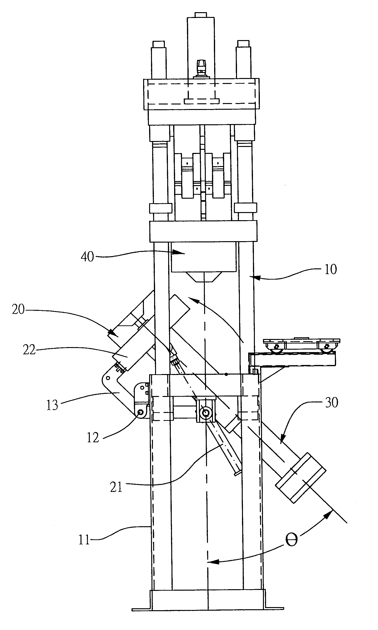
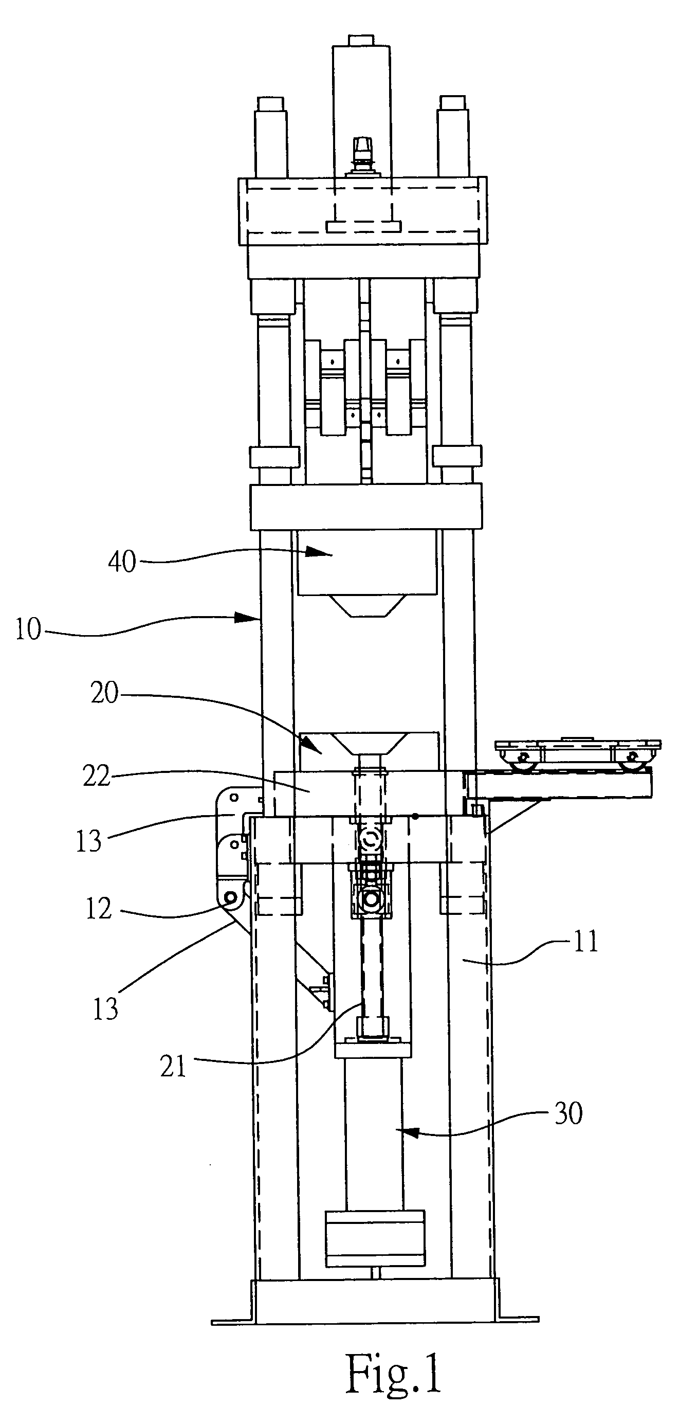
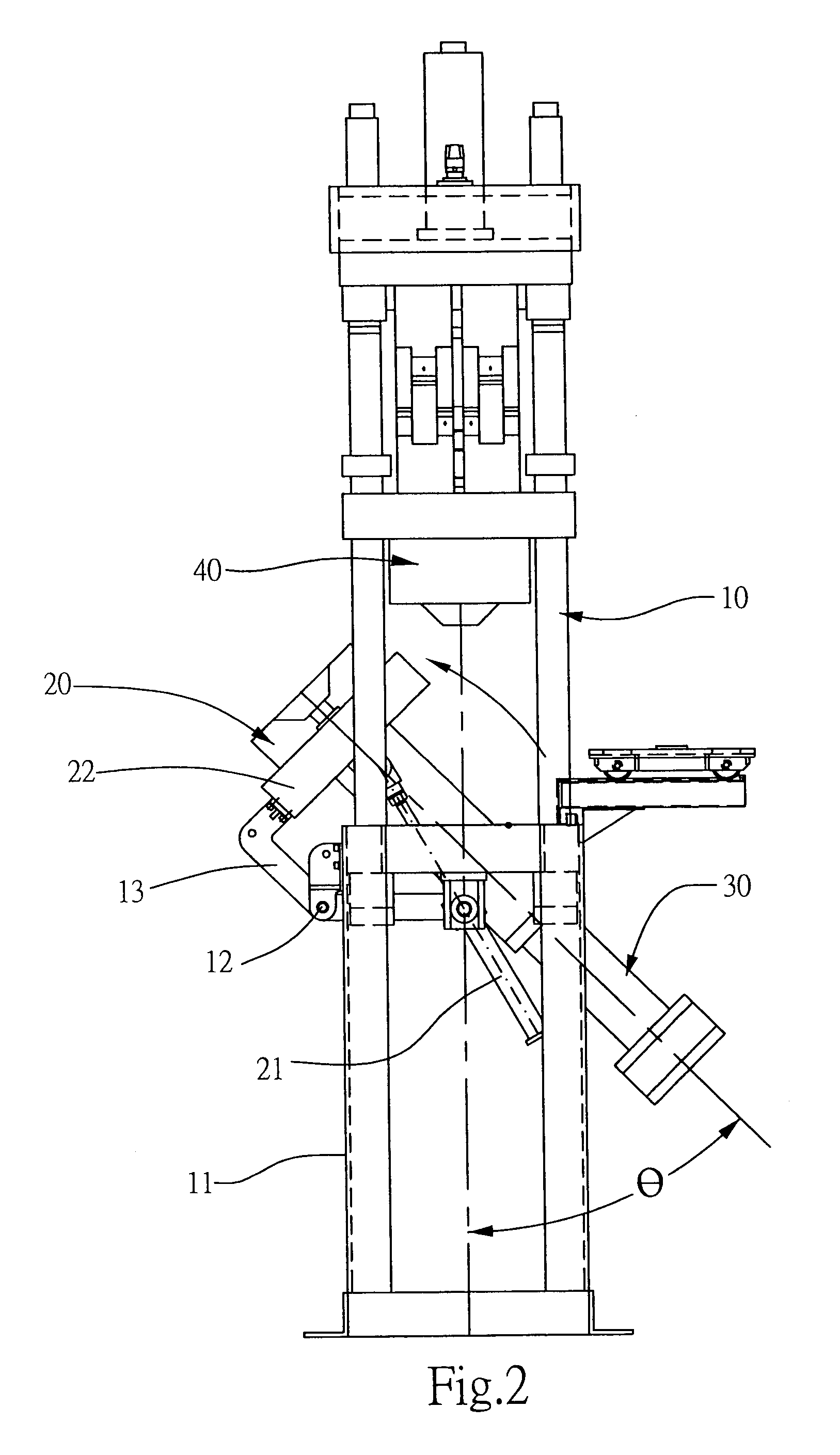
[0015]Referring to FIG. 1, a die-casting device according to the invention at least comprises a housing 10 having a seat 11, a lower mold mechanism 20 at the seat 11, an oil-pressured injection mechanism 30 joined with a lower section of the lower mold mechanism 20, an upper mold mechanism 40 correspondingly disposed at an upper section of the housing 10 and driven by an oil-pressured mechanism for up-and-down movements. The invention is characterized that, the lower mold mechanism 20 is devised with an inclined angle θ at an outward direction as shown in FIG. 2, with the angle θ preferably ranging between 30 and 50 degrees.

[0016]Referring to FIG. 3, the lower mold mechanism 20 is located at an at a center area of an upper section of the seat 11, and is supported and located using symmetrical oil-press...


PUM

PropertyMeasurementUnit
inclined angleaaaaaaaaaa
angleaaaaaaaaaa

Abstract

A die-casting device at least includes a housing having a seat, a lower mold mechanism at the seat, an oil-pressured injection mechanism joined with a lower section of the lower mold mechanism, and a corresponding upper mold mechanism disposed at an upper section of the housing and driven by an oil-pressured mechanism for up-and-down movements; wherein, the lower mold mechanism is devised as a structure with an outwardly inclined angle. Thus, when adding a metal liquid to the die-casting device, the lower mold mechanism is first inclined outward, such that when the metal liquid is flowed in to a material reservoir of an injection mechanism, a flow speed of the metal liquid is reduced to avoid formation of the bubbles, thereby preventing finished die-casting products from containing bubbles and thus elevating product quality.

Description

BACKGROUND OF THE INVENTION[0001](a) Field of the Invention[0002]The invention relates to a die-casting device, and more particularly, to a lower mold mechanism of an upright die-casting device. The lower mold mechanism is devised as being inclined with an appropriate angle, such that when a metal liquid is filled into a material reservoir at an upper section of an injection mechanism, a flow speed thereof is reduced to avoid formation of bubbles, thereby preventing finished die-casting products from containing bubbles and thus elevating product quality.[0003](b) Description of the Prior Art[0004]A prior die-casting device comprises at least a lower mold mechanism at a seat of a machine body thereof. The lower mold mechanism has a lower section thereof joined with an oil-pressured injection mechanism, and the machine body has an upper section thereof provided with a corresponding upper mold mechanism driven by an oil-pressured mechanism for up-and-down movements. When the lower mold...

Claims


Application Information

Patent Timeline
Patent Type & Authority Patents(United States)
IPC IPC(8): B22D17/12
CPCB22D17/30B22D17/12
Inventor YU, JIH-LEE
Owner YU JIH LEE
Why Eureka
Try Eureka