Valve arrangement for a vacuum pump

a vacuum pump and valve arrangement technology, applied in the direction of lift valves, valve details, functional valve types, etc., can solve the problems of poor springing action of o-rings, serious drawbacks of all known designs, and malfunction, so as to improve springing action, eliminate wear, and different elasticities

Inactive Publication Date: 2006-05-02
PFEIFFER VACUUM GMBH
View PDF13 Cites 0 Cited by
  • Summary
  • Abstract
  • Description
  • Claims
  • Application Information

AI Technical Summary

Benefits of technology

[0010]The advantage of the valve spring according to the present invention consists in that it eliminates wear associated with the use of metallic components. The different shapes of the hollow body ensure much better springing action than a solid body O-spring. The deformation range of the hollow body according to the present invention is also much greater than that of a solid body O-ring. On the other hand, less force is required for its deformation. The hollow body can be formed of different elastomeric materials having different elasticities which are widely available on the market. Also, the geometrical dimensions such as the diameter, wall thickness, length can be varied without any problem, which permits to easily adapt spring constants, e.g., stiffness, for different requirements. When the range of the springing action is so reduced that the inner diameter is extremely small but is not zero, no fatigue occurs, and the service life is almost unlimited. With a plurality of windings (concentric rings or a spiral), the spring force can be substantially increased. With the use of segments, it is possible to lower the force to a very small amount.

Problems solved by technology

However, all of the known design have serious drawbacks.
With metallic springs contacting non-lubricated surfaces, which is the case in vacuum pumps with a dry operation in the compression chamber, the wear of the cooperating elements can lead to their malfunction.
However, such an O-ring is characterized by a poor springing action.
This results in a non-linear springing action and in a very small deformation range.
Such spring elements are very expensive in production.

Method used


Image

  • Valve arrangement for a vacuum pump
  • Valve arrangement for a vacuum pump
  • Valve arrangement for a vacuum pump

Examples


Embodiment Construction

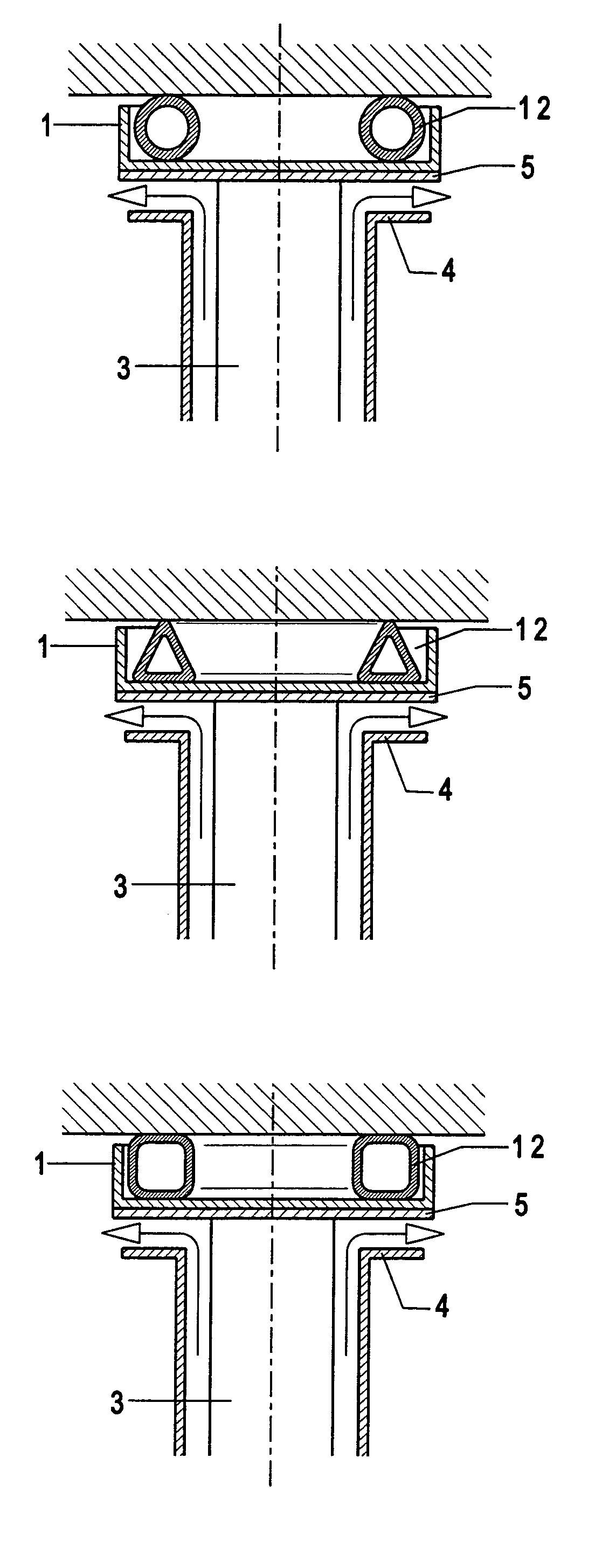
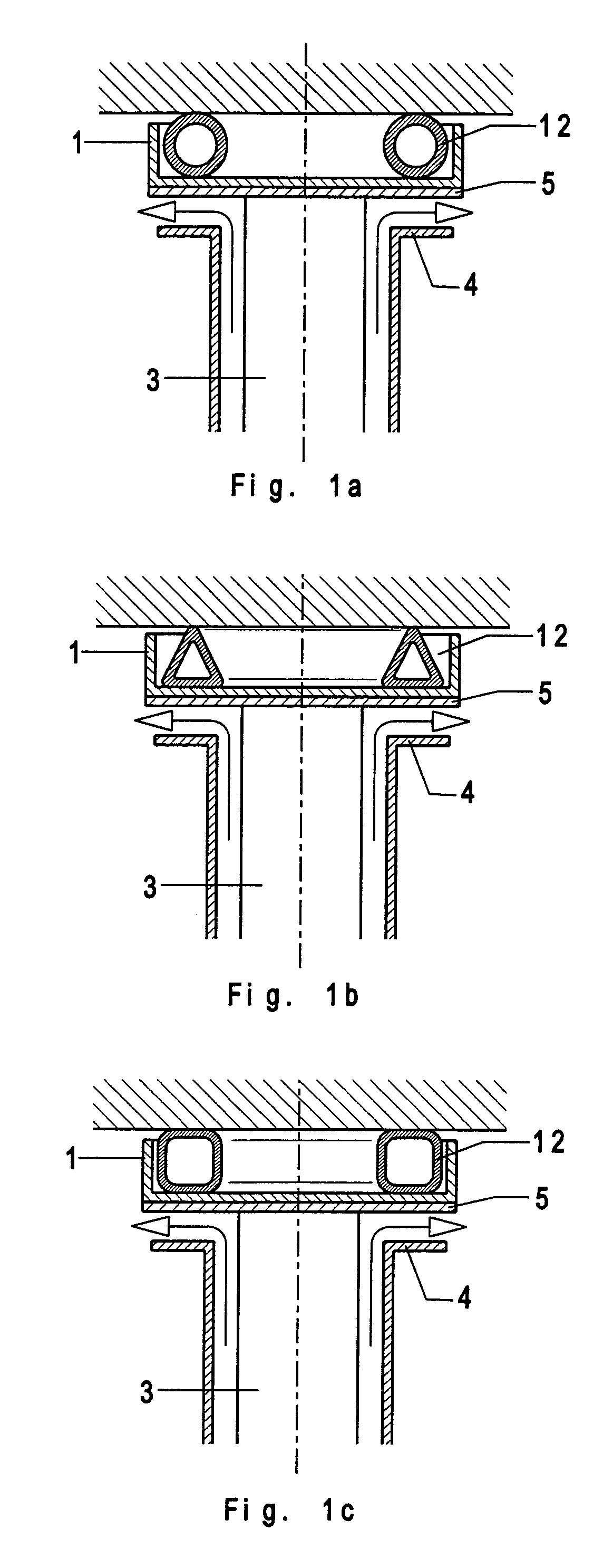
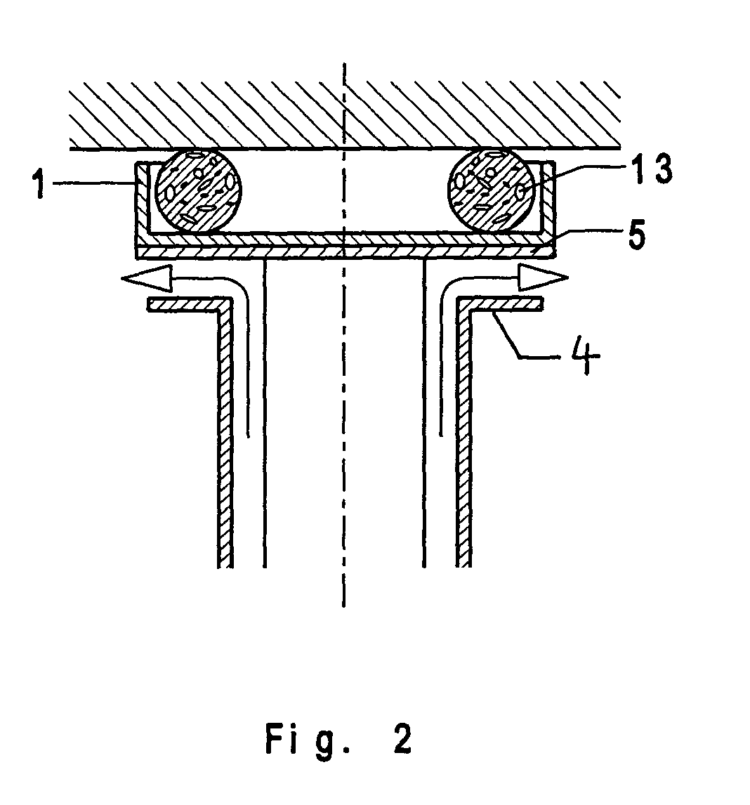
[0021]Valve arrangements according to the present invention, which are shown in FIGS. 1a–1c, include essentially a valve head 1, a valve head support 3, a valve seat 4, and a valve spring 12. The valve head 1 is displaced perpendicular to the flow direction which is shown with arrows. In a closed condition of the valve arrangement, the valve head 1 lies flatly on the valve seat 4. The abutment of the valve head 1 with the valve seat 4 is insured by the valve spring 4 according to the present invention. To provide for an appropriate sealing, the valve head 1 is provided, on its side adjacent to the valve seat 4, with a flat sealing member 5. The sealing member 5 can be formed, e.g., by an appropriate coating.

[0022]According to the present invention, the valve spring 12 is formed as a hollow body, e.g., in form of a section of a tube having different cross-sections. In the embodiment shown in FIGS. 1a, 1b, 1c, the hollow body has, respectively, a circular cross-section, a triangular c...


PUM

PropertyMeasurementUnit
structureaaaaaaaaaa
forceaaaaaaaaaa
shapesaaaaaaaaaa

Abstract

A valve arrangement for a vacuum pump includes a valve head displaceable substantially perpendicular to a flow direction of a fluid through the valve arrangement, a valve seat, and a valve spring for biasing the valve head into a flat abutment engagement with the valve seat, with the valve spring being formed of at least one substantially hollow body made of an elastomeric material.

Description

BACKGROUND OF THE INVENTION[0001]1. Field of the Invention[0002]The present invention relates to a valve arrangement for a vacuum pump and including a valve head displaceable substantially perpendicular to a flow direction of fluid through the valve arrangement, a valve seat, and a valve spring for biasing the valve head into an abutment engagement with the valve seat.[0003]2. Description of the Prior Art[0004]A valve arrangement of the type described above is used primarily in vacuum pumps which are characterized by a dry operation in the compression chamber. The vacuum pumps with a dry operation in the compression chamber necessitate use of lubricant-free components, e.g., valves which are directly connected with the pumps.[0005]Generally, in valves used with the above described type of vacuum pumps, the closing elements which, as a rule, is called a valve head, is displaced in the flow direction. In the closed condition, the valve head flatly abuts a valve seat and is biased to i...

Claims


Application Information

Patent Timeline
Patent Type & Authority Patents(United States)
IPC IPC(8): F16K25/00F16K1/36F04B39/10F04B53/10F16F1/36F16K17/04
CPCF04B39/102F16K17/0493F04B53/102
Inventor BEZ, ECKHARDZABESCHEK, STEFAN
Owner PFEIFFER VACUUM GMBH
Why Eureka
Try Eureka