
Slippage-preventing device for tubular jack

a technology for tubular jacks and jack handles, which is applied to lifting devices, mobile jacks, vehicles with pivoted arms, etc., can solve the problems of structural instability of the combination of tubular handles and conventional jacks, and the tubular handles are likely to slip out of so as to facilitate the assembly and disassembly of the tubular handles and the jack handle stand

Inactive Publication Date: 2006-05-02
SHINN FU
View PDF3 Cites 9 Cited by
  • Summary
  • Abstract
  • Description
  • Claims
  • Application Information

AI Technical Summary

Benefits of technology

"The present invention provides a slippage-preventing device for the tubular handle of a jack. The device consists of a jack handle stand with a movable bar that extends into the inner wall of an insertion hole. The tubular handle has a locking groove and an angled-rim tip. The movable bar is driven back resiliently to lock the tubular handle at the locking groove thereon. The device facilitates the assembly and disassembly of the tubular handle and the jack handle stand. The secondary objective of the invention is to provide a slippage-preventing device for tubular jack handle, wherein the movable bar has an end connecting with a knob cover and the other end forming a blocking piece. A spring is firstly slipped on the movable bar, and the movable bar is then inserted into the opening on jack handle stand through a bar stand, so that the portion of the inner end of the movable bar beyond the blocking piece extends into the insertion hole. The movable bar then connects with the knob cover. The device allows for easy assembly and disassembly of the tubular handle and the jack handle stand. The bar stand can be solidly screwed onto or integrally formed on the jack handle stand. The technical effects of the invention are improved grip and prevention of slippage when using the jack, making it safer and easier to handle."

Problems solved by technology

Since the tubular handle would get rotated during the operation of the jack, the tubular handle is likely to slip out of the jack handle stand.
Therefore, the combination of a tubular handle with a conventional jack is structurally unstable.

Method used


Image

  • Slippage-preventing device for tubular jack
  • Slippage-preventing device for tubular jack
  • Slippage-preventing device for tubular jack

Examples


Embodiment Construction

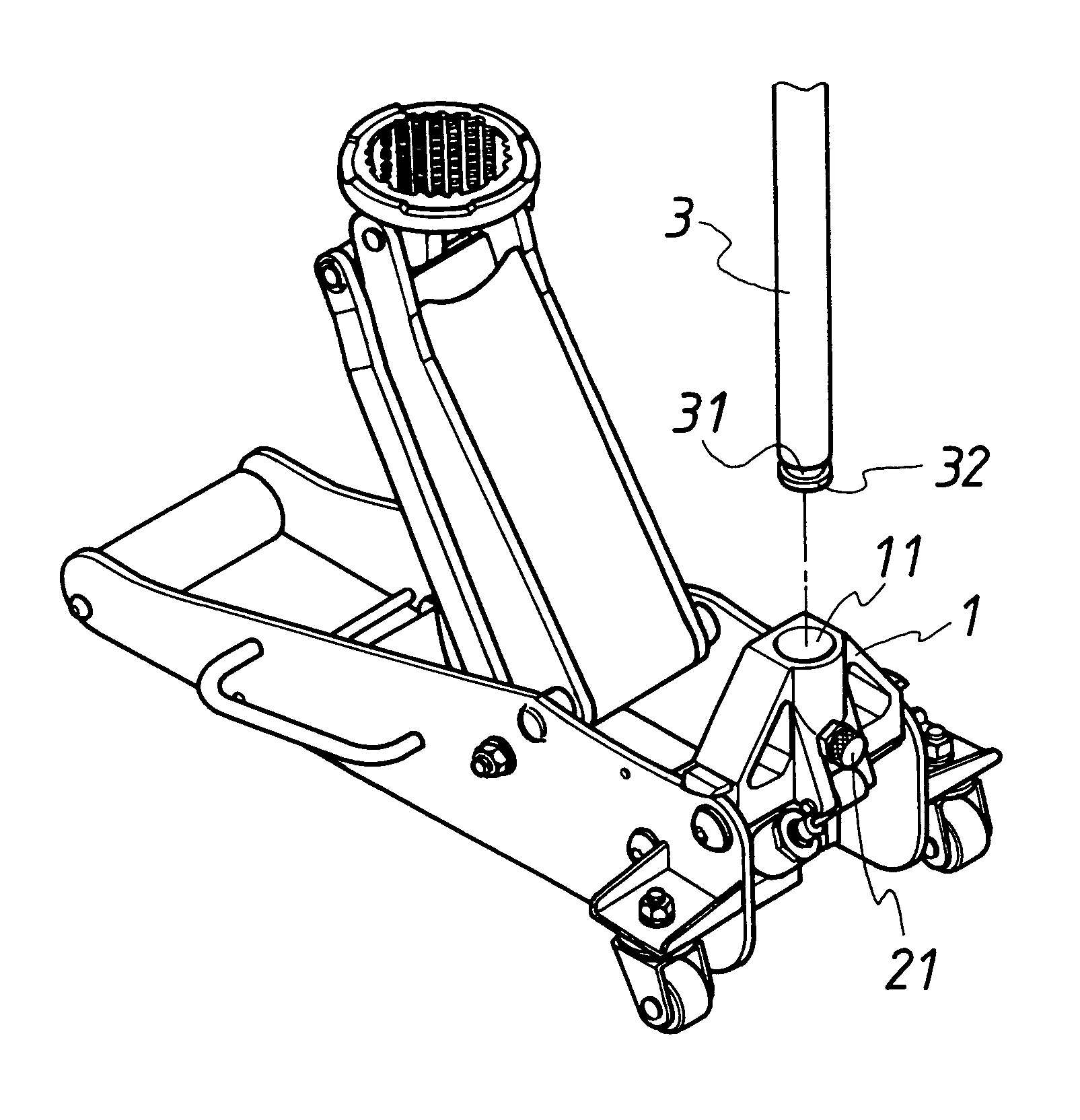
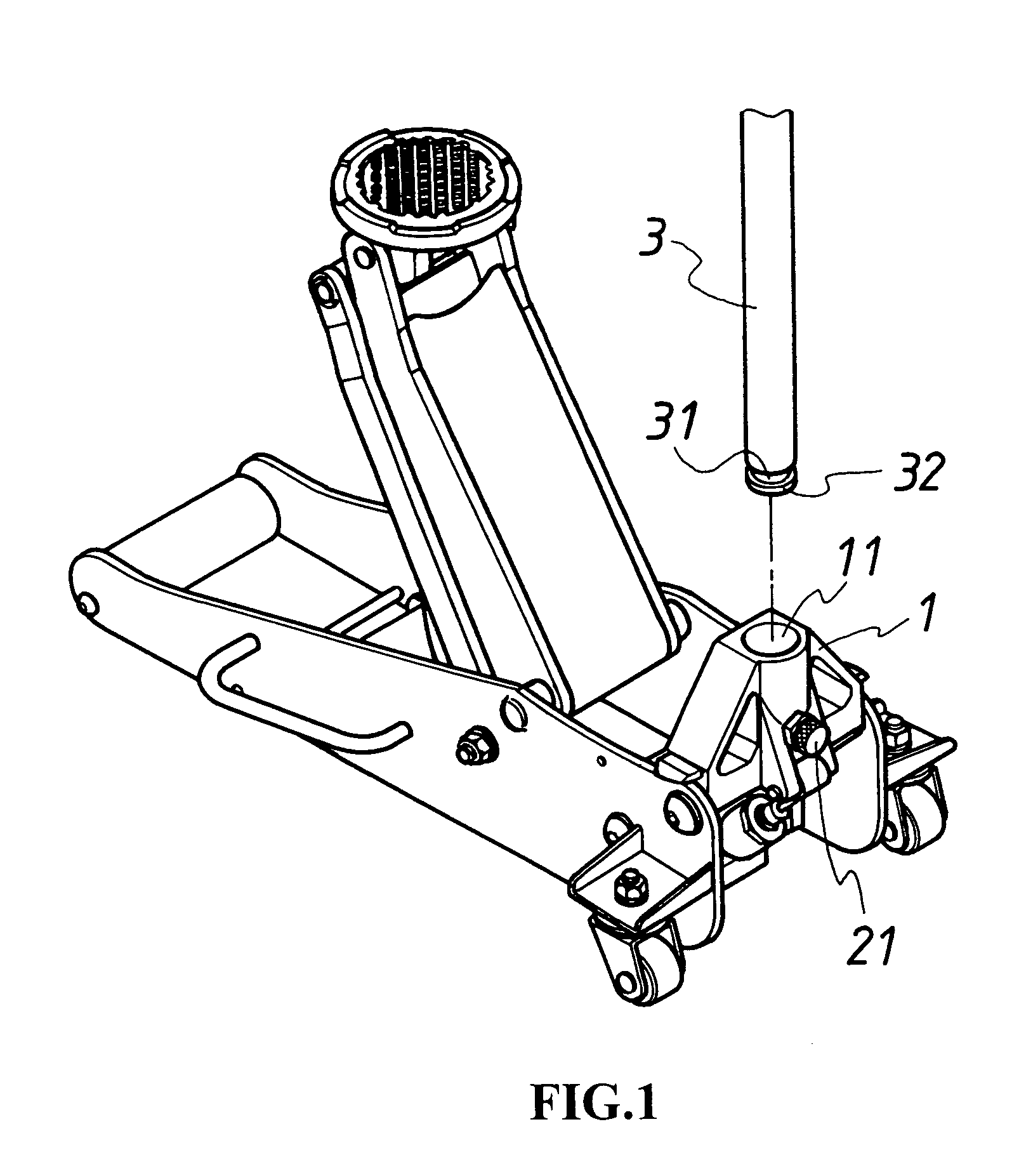
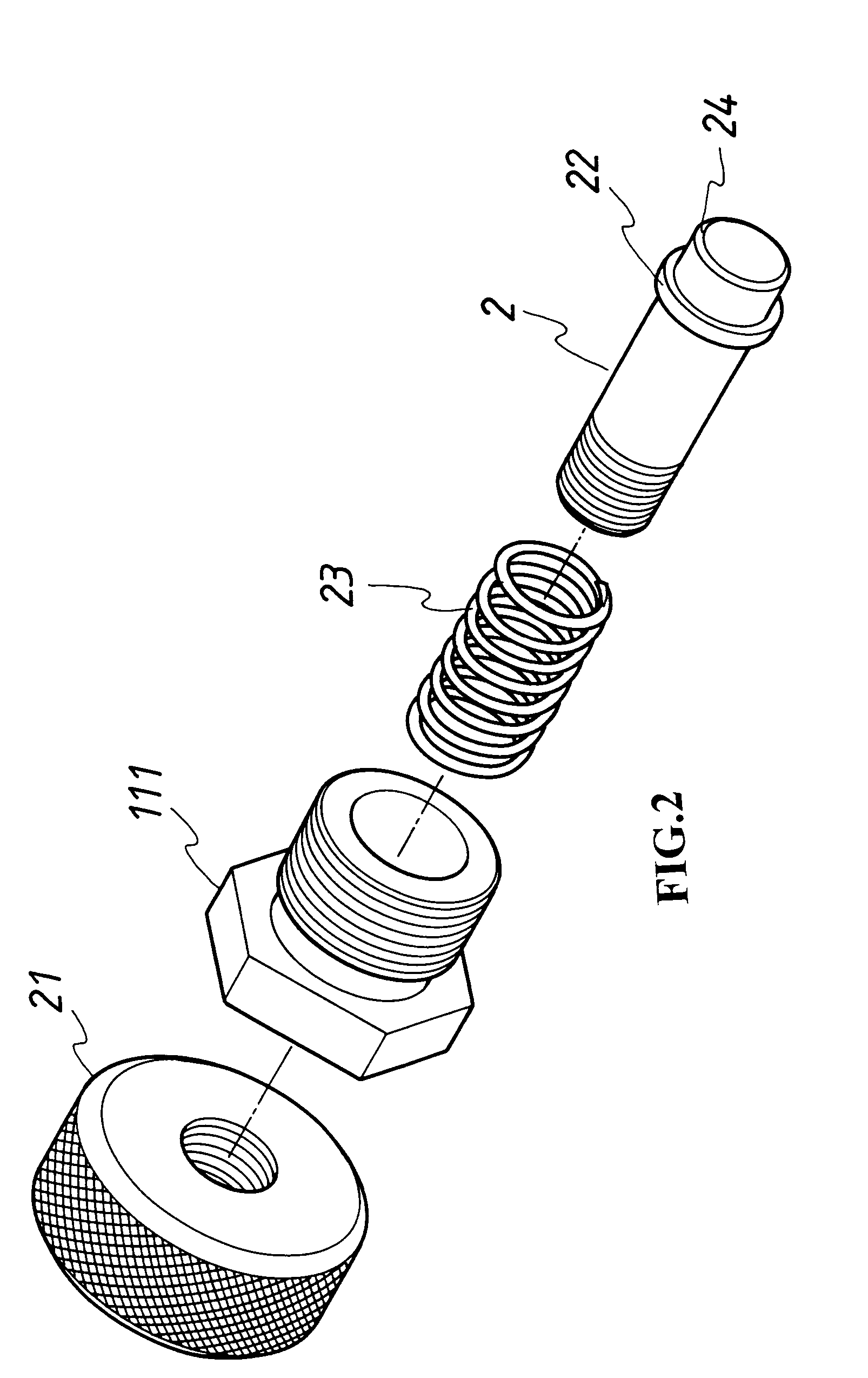
[0016]Referring to FIG. 1, FIG. 2 and FIG. 3, the present invention of a slippage-preventing device for tubular jack handle utilizes a movable bar 2 capable of inserting into the inner wall of the insertion hole 11 on a jack handle stand 1. To facilitate the engagement of a tubular handle 3 with the movable bar 2 within the insertion hole 11, the tubular handle 3 includes a locking groove 31 and an angled rim 32 integrally formed at a front end thereof. Referring to FIG. 4, as the tubular handle 3 enters the insertion hole 11 on the jack handle stand 1, the angled rim 32 firstly pushes aside the movable bar 2, and, as the tubular handle 3 goes deeper, the movable bar 2 bounces back to be engaged with the locking groove 31, so that the tubular handle 3 is substantially locked with the jack handle stand 1, as shown in FIG. 5. As the movable bar 2 is driven backward, the locking mechanism is removed and therefore the tubular handle 3 can be drawn from the jack handle stand 1 easily.

[00...


PUM


Abstract

A slippage-preventing device for tubular jack handle consists of a jack handle stand that is provided with a movable bar extending into the inner wall of an insertion hole therein. A tubular handle has a front end, which is provided with a locking groove and an angled-rim tip. As the tubular handle is inserted into the insertion hole, the angled-rim tip at the front end firstly pushes the movable bar aside, and as the insertion is completed, the movable bar is driven back resiliently to lock the tubular handle at the locking groove thereon. The locking mechanism can be removed by pulling outward the movable bar. This mechanism facilitates the assembly and disassembly of the tubular handle and the jack handle stand.

Description

BACKGROUND OF THE INVENTION[0001](a) Field of the Invention[0002]The present invention relates to slippage-preventing devices for tubular jack handle, and more particularly to a slippage-preventing device for tubular jack handle which is provided with a movable bar within the handle insertion hole, for facilitating the assembly and disassembly of a tubular handle and a jack handle stand.[0003](b) Description of the Prior Art[0004]The jacks of the prior art utilize a tubular handle having a salient object and a handle insertion hole containing an L-shaped indentation on the inner wall thereof. After inserting the tubular handle into the insertion hole and rotating the handle to a proper angular position, the salient object is locked into the L-shaped indentation, which completes the combination of the tubular handle and the jack handle stand. Since the tubular handle would get rotated during the operation of the jack, the tubular handle is likely to slip out of the jack handle stand....

Claims


Application Information

Patent Timeline
Patent Type & Authority Patents(United States)
IPC IPC(8): B66F5/04B66F5/00B66F13/00
CPCB66F13/00B66F5/00
Inventor LIU, GUANG BIN
Owner SHINN FU
Learn More