Display system
a display system and display technology, applied in the field of display systems, can solve the problems of burdensome operation for the viewer and the difficulty of viewing the video presented by the second display system
- Summary
- Abstract
- Description
- Claims
- Application Information
AI Technical Summary
Benefits of technology
Problems solved by technology
Method used
Image
Examples
first embodiment
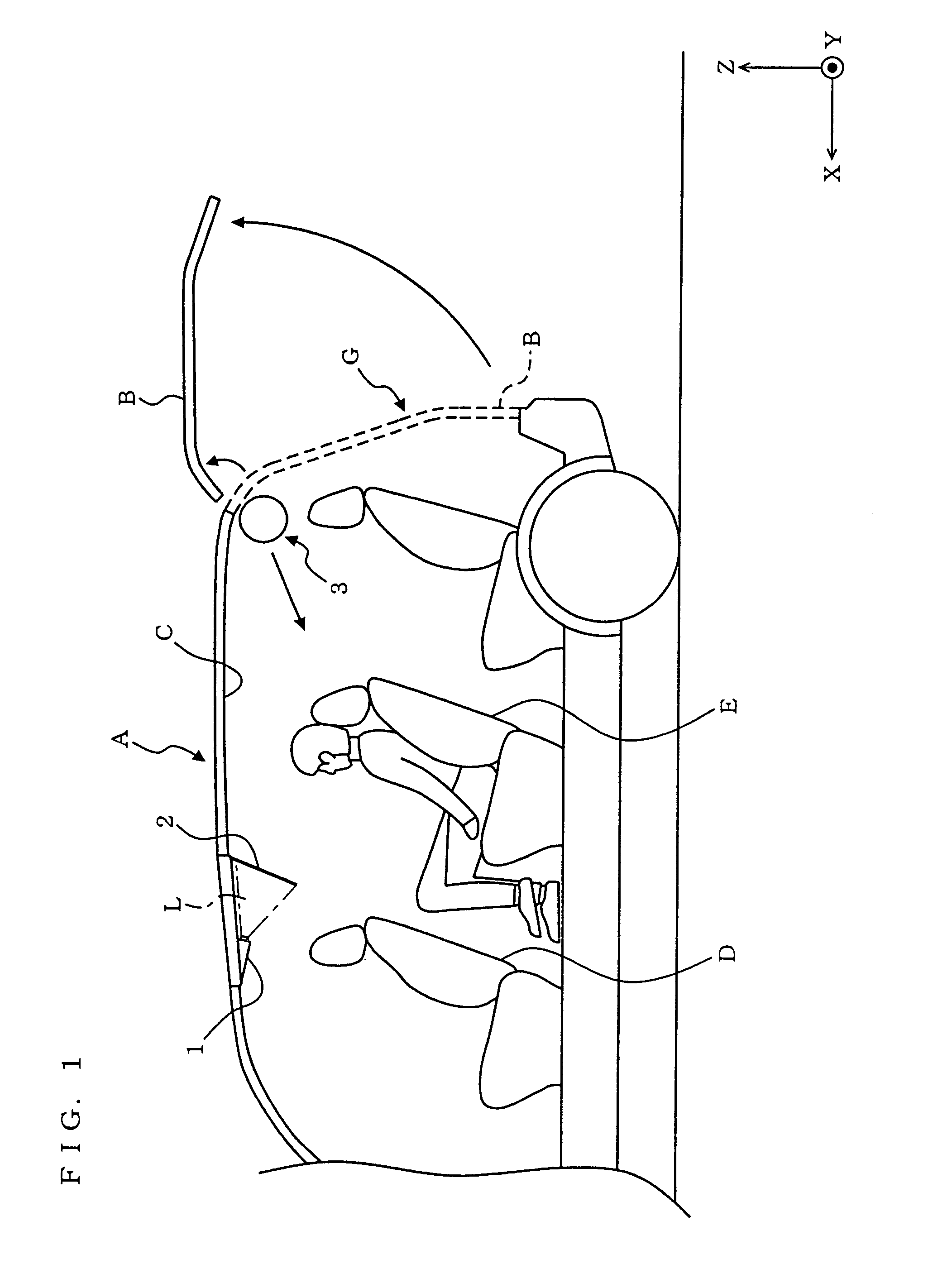
[0078]FIG. 1 is a schematic view illustrating the entire configuration of a display system according to a first embodiment of the present invention. For the sake of convenience of description, FIG. 1 also shows an orthogonal coordinate system having an X axis which is indicative of a traveling direction of a vehicle A, a Y axis which is indicative of a right-hand direction with respect to the traveling direction of the vehicle A, and a Z axis which is indicative of a vertical direction.
[0079]In FIG. 1, the display system is typically mounted on the vehicle A having a back door B or a rear hatch B. Examples of the vehicle A include a sedan with five doors, a station wagon (estate car) with five doors, an SUV (Sports Utility Vehicle), and a four-wheel drive car. The display system provides images to a viewer sitting in a rear seat E of the vehicle A or a viewer outside the vehicle A.
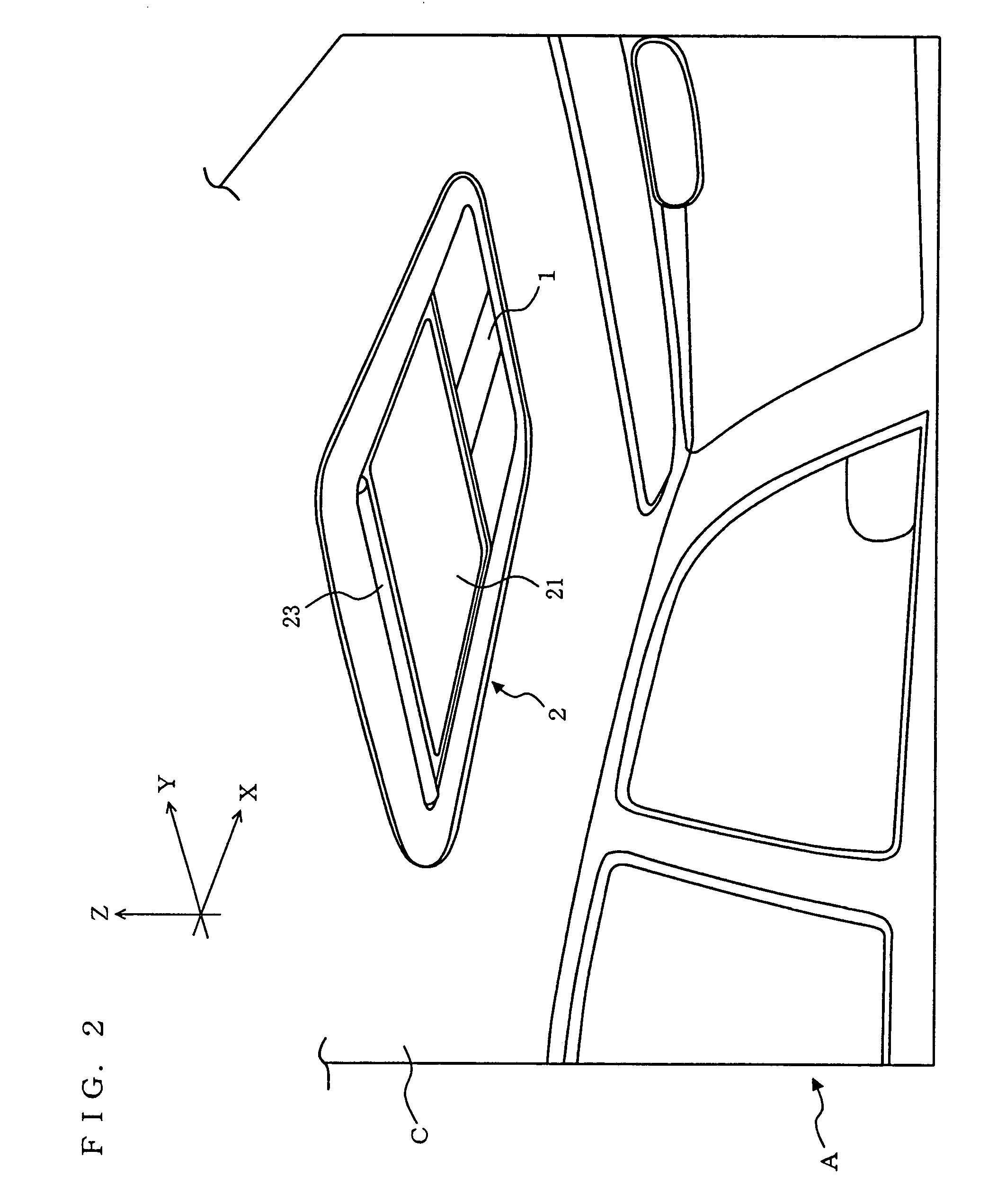
[0080]In order to provide images, the display system includes a projector 1, an interior screen device ...
second embodiment
[0167]FIG. 20 is a schematic diagram illustrating the entire structure of a screen device according to a second embodiment of the present invention. In FIG. 20, the screen device can be applied to a display system mounted on a vehicle, and the screen device includes a mounting member 101, a supporting member 102, a body 103, a screen 104, and a light shield (preferably, two light shields as shown in FIG. 20) 105, and several (two in FIG. 20) hinges 106.
[0168]The mounting member 101 is structured so as to be mountable on the ceiling inside a vehicle. Unlike the first embodiment, in the second embodiment, the vehicle can be of any type. The mounting member 101 further includes a rotational shaft 1011 for rotating the supporting member 102 about its longitudinal axis. The rotational shaft 1011 rotates in a vertical plane at angles up to a predetermined angle θ.
[0169]The supporting member 102 has a rod-like shape, and is structured so as to be able to extend and retract within a range o...
third embodiment
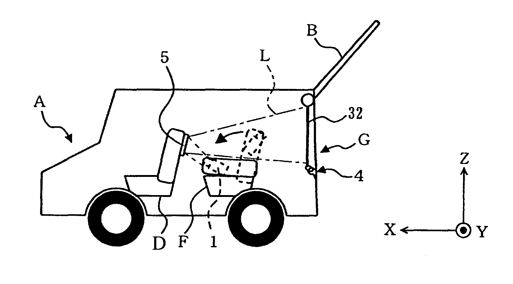
[0325]FIG. 38 is a schematic illustration showing the entire configuration of a display system according to a third embodiment of the present invention. FIG. 39 is a perspective view of a part of the display system illustrated in FIG. 38 when viewed from the left rear angle of a vehicle A. For the sake of convenience of description, each of FIGS. 37 and 38 also shows an orthogonal coordinate system having an X axis, a Y axis, and a Z axis.
[0326]In FIGS. 37 and 38, the display system is typically mounted on the vehicle A. In the present embodiment, the vehicle A is not restricted to the types of vehicle described in the first embodiment, but may be any type of vehicle. This display system includes a projector 10001, a screen 10002 (not shown in FIG. 39), a reflecting member 10003, and a supporting member 10004.
[0327]The projector 10001 is mounted typically between front seats D and rear seats E on the floor of the vehicle so as to be able to emit a light beam L generated by the proje...
PUM
 Abstract
Description
Claims
Application Information
 - R&D
- Intellectual Property
- Life Sciences
- Materials
- Tech Scout
- Unparalleled Data Quality
- Higher Quality Content
- 60% Fewer Hallucinations
Browse by: Latest US Patents, China's latest patents, Technical Efficacy Thesaurus, Application Domain, Technology Topic, Popular Technical Reports.
© 2025 PatSnap. All rights reserved.Legal|Privacy policy|Modern Slavery Act Transparency Statement|Sitemap|About US| Contact US: help@patsnap.com


