AI technical title is built by PatSnap AI team. It summarizes the technical point description of the patent document.
a thrombosis and thrombosis technology, applied in the field of vascular devices, can solve the problems of affecting the function of the vein, the damage of the vein, and the inability to use,
Inactive Publication Date: 2006-05-02
ARGON MEDICAL DEVICES
View PDF369 Cites 165 Cited by
Summary
Abstract
Description
Claims
Application Information
AI Technical Summary
This helps you quickly interpret patents by identifying the three key elements:
Problems solved by technology
Method used
Benefits of technology
Problems solved by technology
Since this approach requires multiple needle sticks in the vein to withdraw and return the blood, the vein can eventually be damaged beyond usability, blood clots can form and the vein can fail.
These agents, however, are expensive, require lengthier hospital procedures and create risks of drug toxicity and bleeding complications as the clots are broken.
This multiple wire device is expensive and can be traumatic to the graft, possibly causing damage, since as the basket rotates, the graft is contacted multiple times by the spinning wires.
Other risks associated with the basket include the possibility of catching onto the graft itself and tearing the graft as well as catching and tearing the suture at the anastomotic site.
Additionally, the basket can become filled with a clot which would then require time consuming withdrawal of the basket, cleaning the basket and reinserting it into the lumen.
Method used
Image
Click on the blue label to locate the original text in one second.
Reading with bidirectional positioning of images and text.
Examples
Embodiment Construction
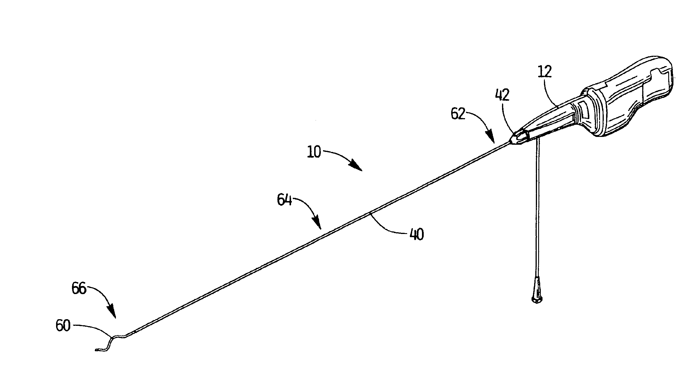
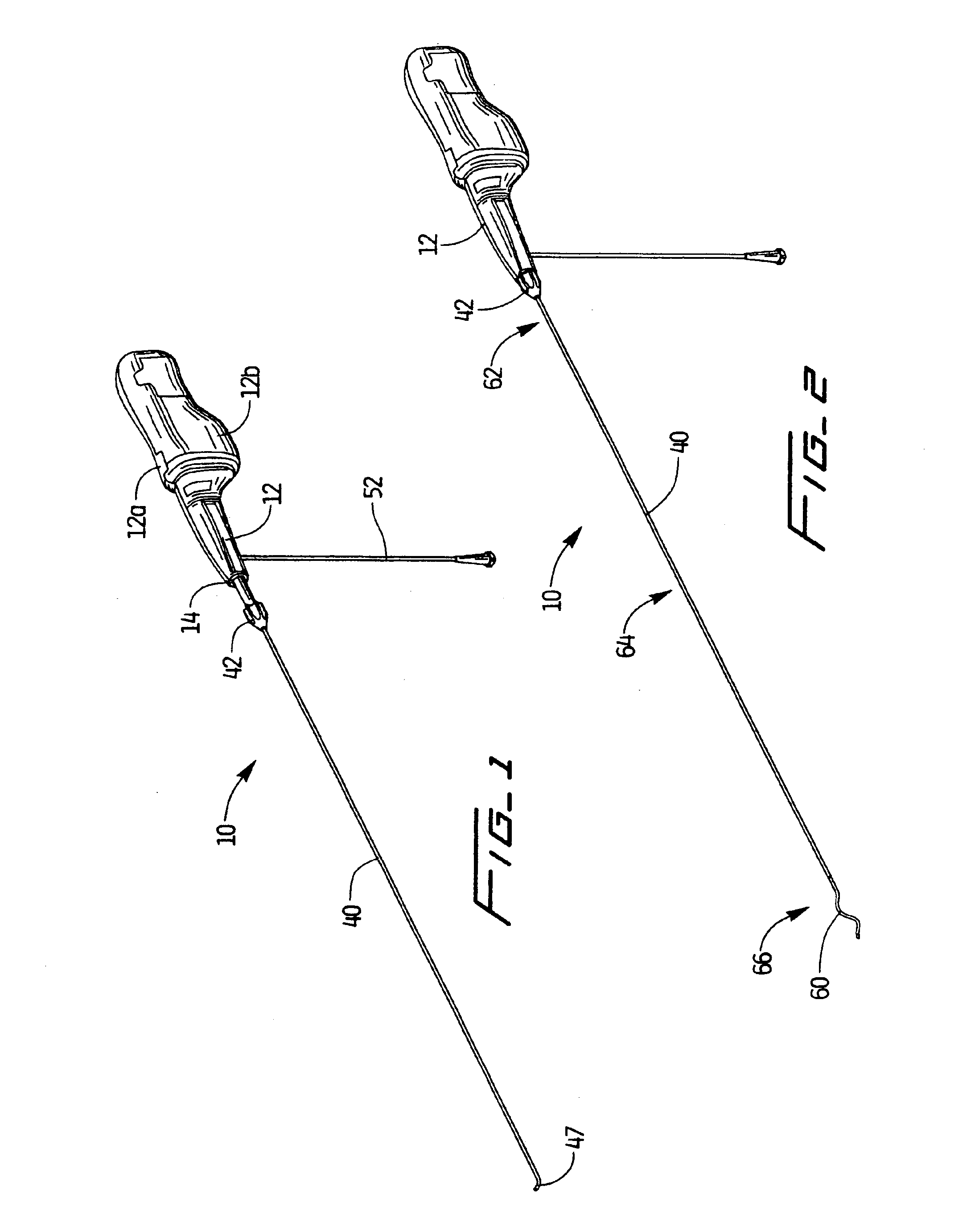
[0060]Referring now in detail to the drawings where like reference numerals identify similar or like components throughout the several views, FIGS. 1 and 2 illustrate a first embodiment of the thrombectomy apparatus of the present invention, designated generally by reference numeral 10.
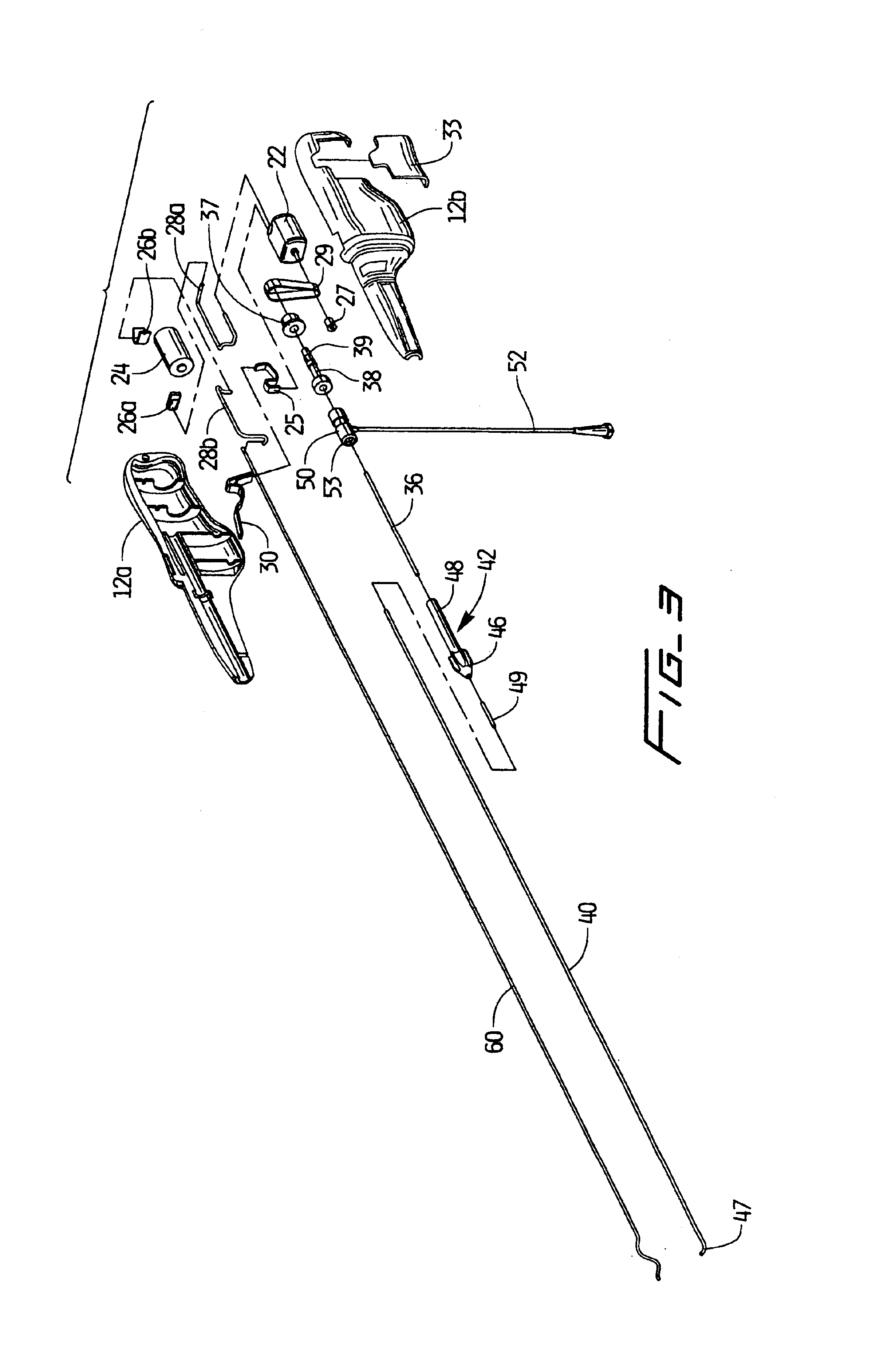
[0061]Apparatus 10 has a housing 12 composed of housing halves 12a, 12b, a flexible tube or sheath 40 and a rotational thrombectomy wire 60 contained within the flexible sheath 40. A knob 42, extending from distal end 14 of housing 12, is attached to the flexible sheath 40 to enable both rotation and sliding movement of the flexible sheath (tube) 40 with respect to the wire which is fixed axially. Note that although the flexible sheath 40 is shown as slidable and the wire 60 is fixed axially, alternatively, the wire can be axially slidable with the sheath 40 stationary, or both the wire 60 and sheath 40 can be slidable. In any case, relative movement of the wire 60 and sheath 40 will enable the wire 6...
PUM
Abstract
A thrombectomy apparatus for breaking up thrombus or other obstructive material in a lumen of a vascular graft or vessel comprising a flexible sheath, and a wire positioned within the flexible sheath wherein the wire and flexible sheath are relatively movable. The wire is substantially sinuous in configuration and assumes a substantially sinuous shape when in the deployed position and assumes a straighter position in the retracted position. The wire is operatively connected to a motor for rotation of the wire to enable peaks of the sinuous wire to contact a wall of the lumen to break up the thrombus or other obstructive material.
Description
[0001]This application is a continuation-in-part of application Ser. No. 09 / 502,261, filed Feb. 11, 2000, now U.S. Pat. No. 6,602,264, which is a continuation of application Ser. No. 09 / 122,483, filed Jul. 23, 1998, now U.S. Pat. No. 6,090,118, which claims priority from provisional application Ser. No. 60 / 053,475 filed Jul. 24, 1997, and is a continuation-in-part of application Ser. No. 09 / 888,149 filed Jun. 22, 2001, which is a continuation-in-part of International Application No. PCT / US00 / 41355, filed Oct. 20, 2000, which claims priority from provisional application Ser. Nos. 60 / 161,124, filed Oct. 22, 1999, and 60 / 214,331, filed Jun. 27, 2000. The entire contents of these applications are incorporated herein by reference.BACKGROUND[0002]1. Technical Field[0003]This application relates to a vascular device and more particularly to a rotational thrombectomy device for clearing thrombus from dialysis grafts.[0004]2. Background of Related Art[0005]Hemodialysis is a well-known method...
Claims
Application Information
Patent Timeline
Application Date:The date an application was filed.
Publication Date:The date a patent or application was officially published.
First Publication Date:The earliest publication date of a patent with the same application number.
Issue Date:Publication date of the patent grant document.
PCT Entry Date:The Entry date of PCT National Phase.
Estimated Expiry Date:The statutory expiry date of a patent right according to the Patent Law, and it is the longest term of protection that the patent right can achieve without the termination of the patent right due to other reasons(Term extension factor has been taken into account ).
Invalid Date:Actual expiry date is based on effective date or publication date of legal transaction data of invalid patent.

