Passive apparatus that regulates a flow of heated air within a plasma display device

a plasma display device and passive technology, applied in the field of passive apparatus, can solve the problems of high temperature of heat generated at specific areas of the plasma display device, user safety risks, and hot air emerging from such components can harm users

Inactive Publication Date: 2006-05-02
SAMSUNG SDI CO LTD
View PDF17 Cites 14 Cited by
  • Summary
  • Abstract
  • Description
  • Claims
  • Application Information

AI Technical Summary

Benefits of technology

[0011]It is therefore an object of the present invention to provide an improved design for a plasma display device.
[0012]It is yet another object of the present invention to provide designs for a plasma display device that better manages the air currents within the device in such a manner that prevents a user in the vicinity of the device or a user that touches the device from being burned or harmed by extreme heat.
[0013]It is further an object of the present invention to moderate the temperature of extremely hot air generated within a functioning plasma display prior to when the air exits the plasma display.

Problems solved by technology

However, with the use of separate elements such as heat pipes and heat sinks to dissipate the heat in the plasma display device, although some degree of cooling can be expected through such elements, heat generated at specific areas of the plasma display device can reach excessively high temperatures.
This may pose safety risks to users considering that the drive circuits (e.g., the switching mode power supply board or SMPS board) operate at temperatures of up to 90° C. Unless the air heated by such circuit elements is cooled or dispersed before exiting from the plasma display device, the hot air emerging from such components can harm a user that should happen to touch the plasma display panel or should happen to place the user's hands in the vicinity of where the hottest air exits from the inside of the plasma display device.
In other words, if the convective air currents within a functioning plasma display device are not managed properly, certain portions on the upper edge of the plasma display device and air emerging from these certain portions on the upper edge of the plasma display device can reach excessively high temperatures and thus cause a safety hazard to users who may come into close contact with the plasma display device.
Especially immediately above a high heat generating component such as the switching mode power supply, the air rising and exiting the plasma display device can be extremely hot.
This temperature disparity along the top edge of the plasma display device, especially when certain portions of the top edge are dangerously hot, needs to be moderated.
Also, there is a need to control the convective air currents within a functioning plasma display device so that portions along an upper edge of the plasma display panel to not reach excessively high temperatures and pose a safety threat to users of the plasma display device.

Method used


Image

  • Passive apparatus that regulates a flow of heated air within a plasma display device
  • Passive apparatus that regulates a flow of heated air within a plasma display device
  • Passive apparatus that regulates a flow of heated air within a plasma display device

Examples


first embodiment

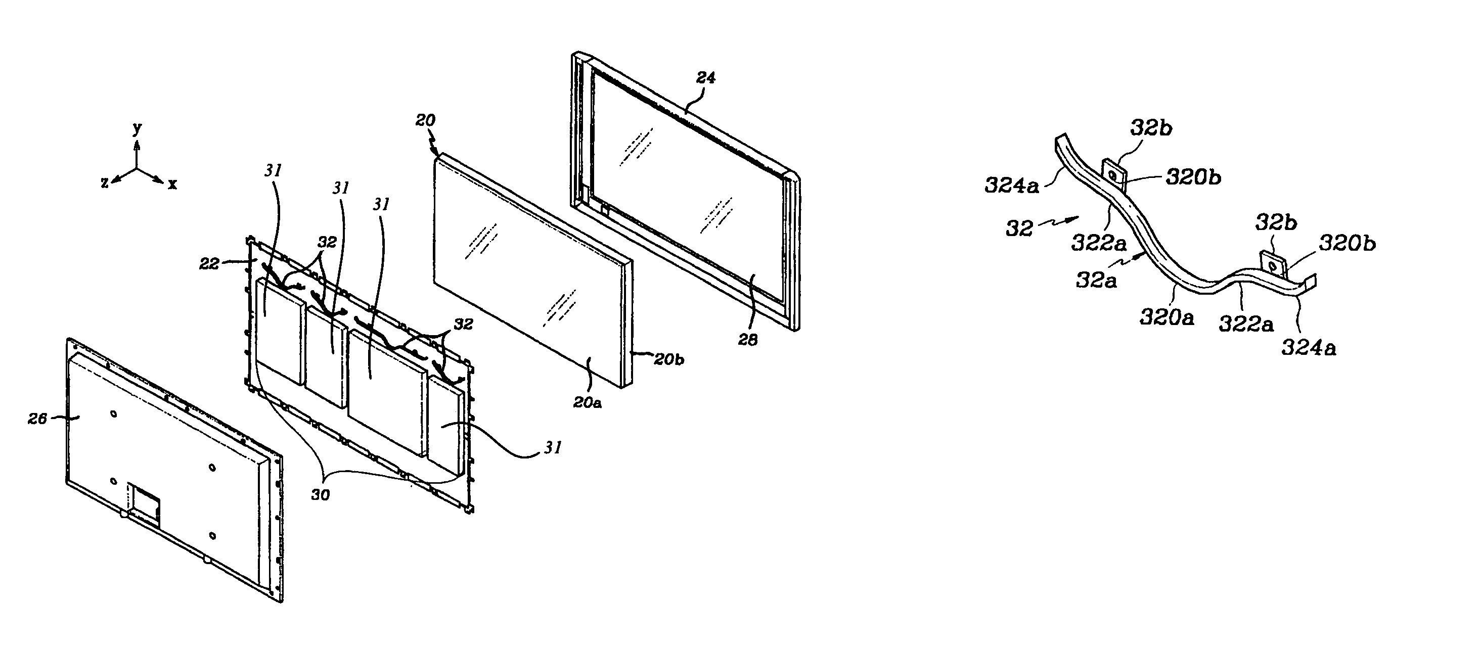
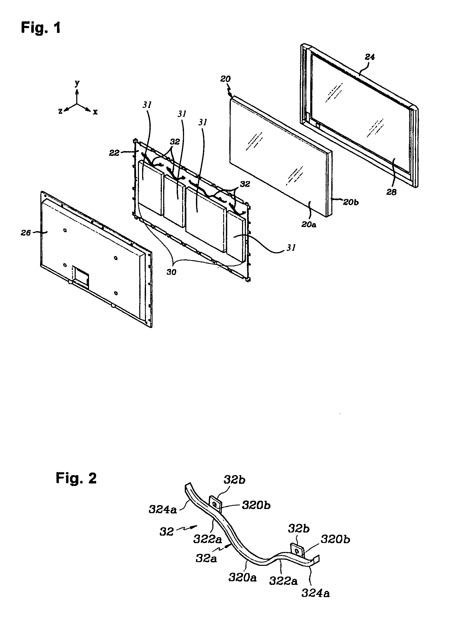
[0052]As illustrated in FIG. 4, each regulating member 32 serves to force the most extreme hottest air rising from the corresponding circuit element 31 of the circuit assembly 30 toward areas that are not directly above a circuit element 31 of the circuit assembly 30 as illustrated by the arrows. The hot air then mixes with the cool air such that the heat at the top of the back cover 26 is more evenly distributed and is moderated. Therefore, when users makes contact with the top of the back cover 26, excessive heat that may cause injury is no longer a problem.

[0053]Additional preferred embodiments will now be described. FIG. 5 is a perspective view of a chassis base according to a second preferred embodiment of the present invention, and is used to describe a mounting of a regulating member to the chassis base. Like reference numerals for elements identical to those described with reference to the first preferred embodiment will be used.

[0054]As illustrated in FIG. 5, a regulating ...

second embodiment

[0057]As illustrated in FIG. 6, with the regulating member 40 structured as described above hot air generated by circuit element 31 of the circuit assembly 30 during operation of the plasma display device rises vertically (+Y direction) to be blocked by the non-aperture portions 400a of the regulating member 40. As a result, the air is forced in a + / −X direction (sideways or laterally) toward the aperture portions 402a causing the hot air to mix with the relatively cool air in this area, then this mixed air passes through the apertures 404a. This results in a more even distribution of temperature at a top of a back cover 26 while preventing extreme heat from emerging at the top of the back cover 26.

[0058]FIG. 7 is a perspective view of a chassis base according to a third preferred embodiment of the present invention. Like reference numerals for elements identical to those described with reference to the first preferred embodiment will be used. As illustrated in FIG. 7, a regulating...


PUM


Abstract

A plasma display device that uses a plasma display panel to enable use as an image device such as a television. The plasma display device includes a plasma display panel, a chassis base including a circuit assembly for driving the plasma display panel and regulating members mounted in a vicinity of the circuit assembly on a surface of the chassis base to which the circuit assembly is provided, said regulating members regulating the flow of air in the area of the chassis base.

Description

CLAIM OF PRIORITY[0001]This application makes reference to, incorporates the same herein, and claims all benefits accruing under 35 U.S.C. §119 from an application for PLASMA DISPLAY DEVICE earlier filed in the Korean Intellectual Property Office on Aug. 22, 2002 and there duly assigned Ser. No. 2002-49757.BACKGROUND OF THE INVENTION[0002]1. Field of the Invention[0003]The present invention relates to a plasma display device, and more particularly, to a passive apparatus that manipulates the flow of heated air within a plasma display device preventing parts of the display panel and any air from reaching an extremely high temperature during the functioning of the plasma display device.[0004]2. Description of the Related Art[0005]It is well known that heat is generated in a plasma display panel (PDP) of a plasma display device during the functioning of the PDP. Especially in today's more modern PDP's, the amount of gas discharge may be increased in the PDP to improve brightness, there...

Claims


Application Information

Patent Timeline
Patent Type & Authority Patents(United States)
IPC IPC(8): H01J17/49H04N5/66G09F9/00H05K5/02
CPCH05K5/02H01J2217/49H01J11/10H01J17/16
Inventor BAE, SUNG-WONRYU, HO-CHUL
Owner SAMSUNG SDI CO LTD
Why Eureka
Try Eureka