
Magnetic anomaly homing system and method using rotationally invariant scalar contractions of magnetic gradient tensors

a homing system and magnetic gradient technology, applied in the field of magnetic anomaly homing system and method, can solve the problems of reducing the effective range of the sensor, and limiting the mobile magnetic sensing ar

Inactive Publication Date: 2006-05-02
THE UNITED STATES OF AMERICA AS REPRESENTED BY THE SECRETARY OF THE NAVY
View PDF7 Cites 41 Cited by
  • Summary
  • Abstract
  • Description
  • Claims
  • Application Information

AI Technical Summary

Benefits of technology

[0012]Other objects and advantages of the present invention will become more obvious hereinafter in the specification and drawings.
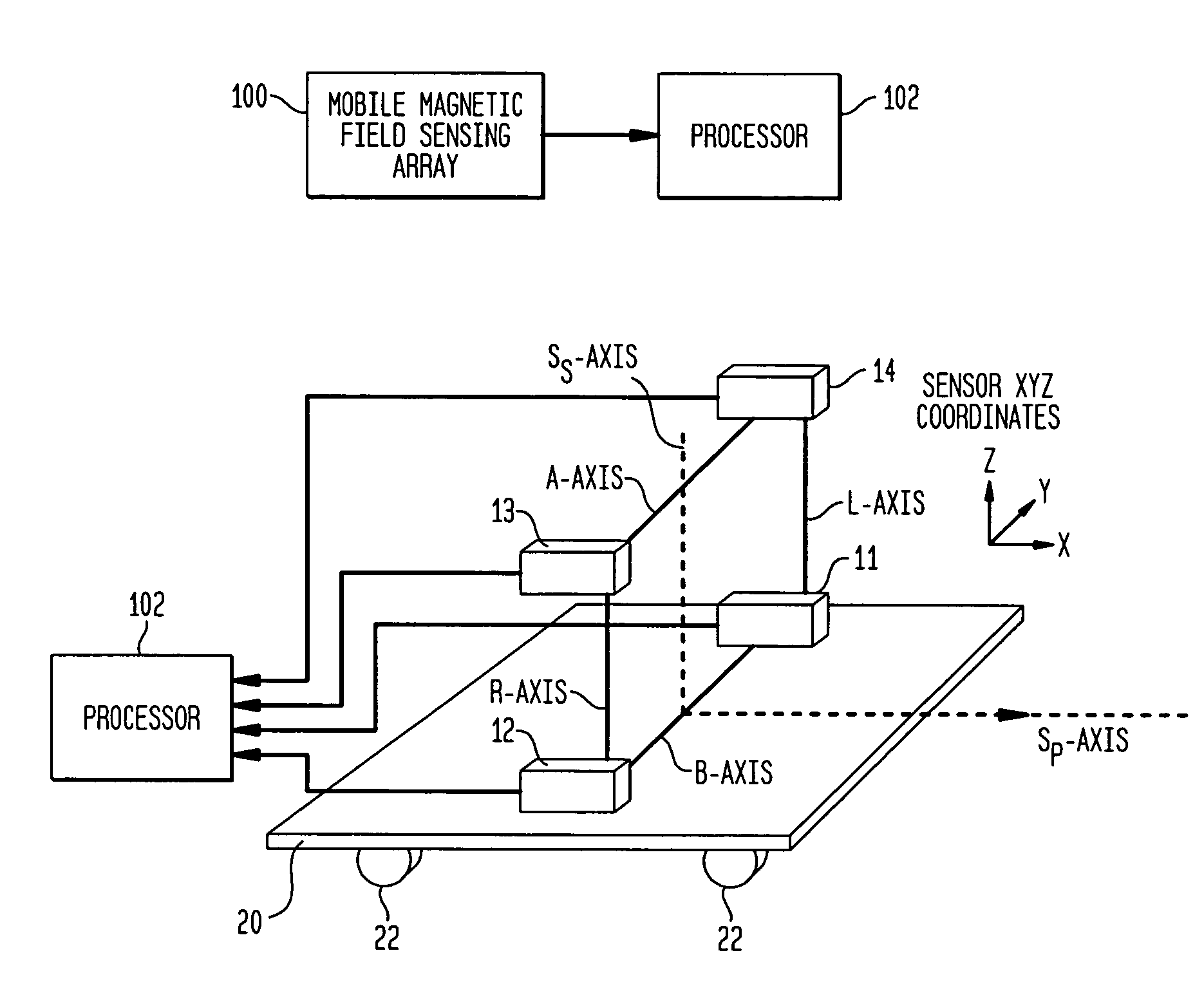
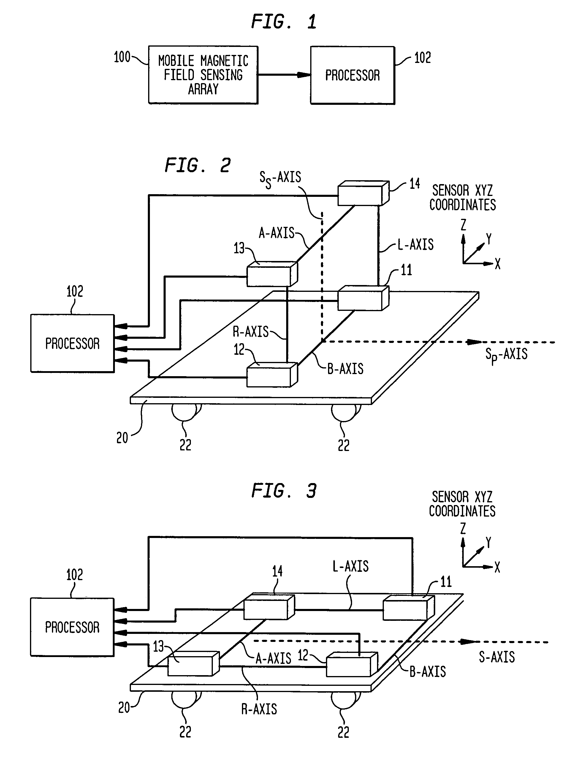
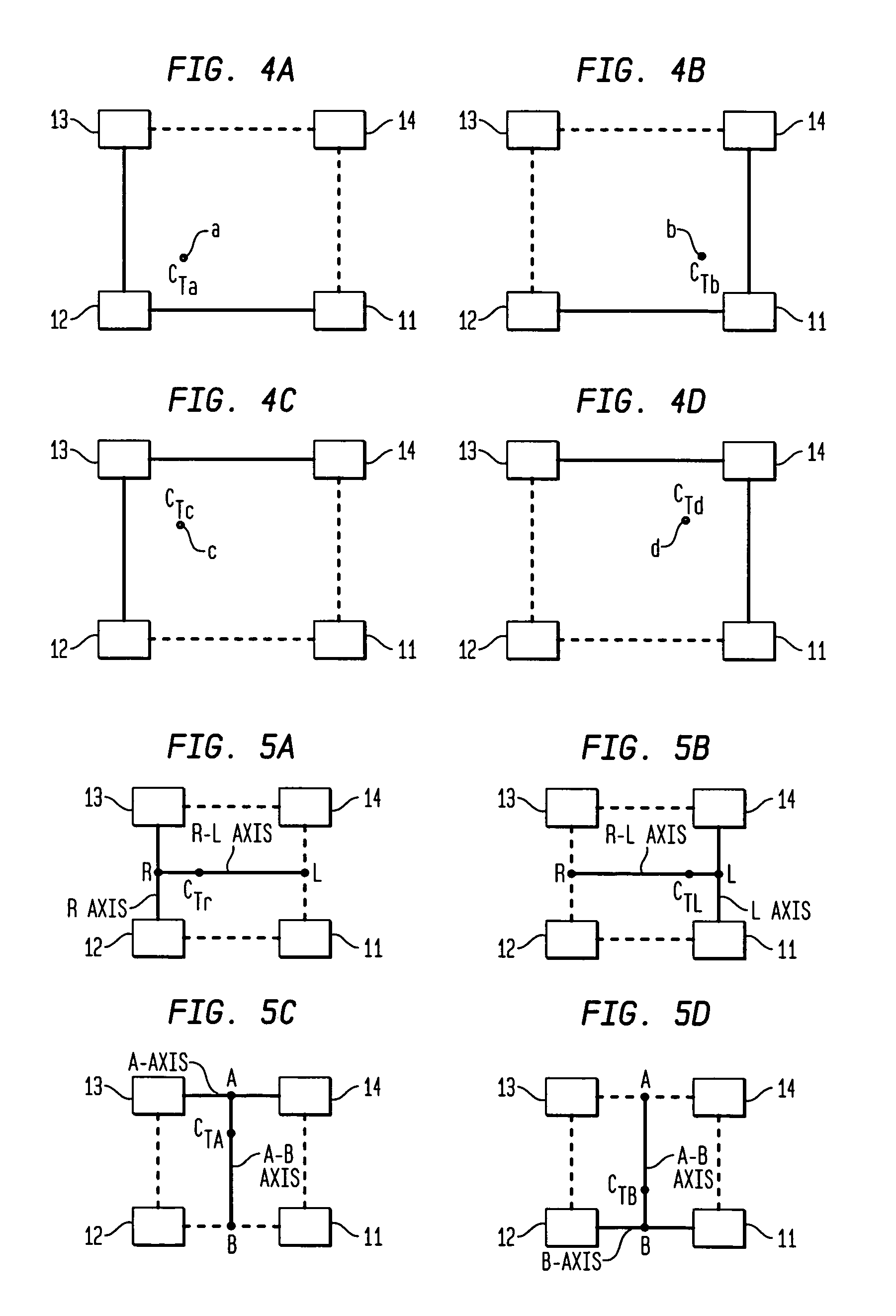
[0013]In accordance with the present invention, a magnetic anomaly homing system and method utilize a planar array of four triaxial magnetometer (TM) sensors coupled to a non-magnetic platform. The four TM sensors are positioned at the vertices of a rectangular parallelogram that lies in a plane that is either (i) parallel to a direction of motion of the platform, or (ii) perpendicular to the platform's direction of motion. Each of the four TM sensors senses a magnetic field thereat due to the presence of a magnetic anomaly. The sensed magnetic field is defined in terms of the field's three mutually orthogonal dimensional components. The magnetic field sensed at the four TM sensors is processed to generate complete gradient tensors and corresponding scalar gradient contractions thereof for four two-axis gradiometers formed by the array. The scalar gradient contractions for each of the four two-axis gradiometers use magnetic field data associated with endpoints of two nonparallel axes of the array. The scalar gradient contractions define guidance control parameters used to steer the platform toward the magnetic anomaly.

Problems solved by technology

In practice, however, the mobile magnetic sensing art has been limited by the fact that the very small magnetic signals of magnetic objects are convolved within the much larger background magnetic field of the Earth.
As a result, a basic challenge for mobile magnetic sensors is the need to discriminate the very small DC target signature components that are convolved with the relatively very large field of Earth.
Sensor motion in the very large Earth field can cause relatively huge, orientation-dependent changes in measured vector field components.
The large, non-target-related changes in measured field components can overwhelm the relatively small target signatures and thereby reduce the sensor's effective range.
For small autonomous mobile sensing systems, size constraints require that the magnetic sensors be small and operate well with small power and computational budgets.
Still further, the operational constraints that are imposed by the naval diving environment largely preclude the practical use of conventional prior art magnetic sensor systems and methods based on magnetic scalar total field or magnetic vector / gradient tensor technologies.
However, the '610 patent does not provide explicit magnetic guidance parameters that can readily be used by an autonomous vehicle to home in on magnetic mines.
Further, the '610 patent discloses sensor systems and target localization methods that are too complex and inefficient for direct target-homing guidance.
In addition, the partial gradient contraction subsets disclosed in the '610 patent do not provide an optimal parameter basis for homing in on targets of any orientation.
However, for a certain range of target and sensor orientations, the sensor system embodiments and gradient processing methods that are disclosed in the '493 application may not provide optimal target-homing capabilities.
Still further, the sensor system embodiments and methods disclosed in the '493 application do not provide robust indications of a mine's vertical position relative to the sensing platform.
That is, the '493 application does not disclose a method to explicitly determine whether a target is buried below the level of the searching platform or tethered above the searching platform.
However, while the magnetic sensor systems and methods taught by the '481 application have many advantages for DLC of mines using high-mobility sensing platforms, the sensor system embodiments disclosed thereby are more complex than necessary for simple guidance of a vehicle to a magnetic target.

Method used


Image

  • Magnetic anomaly homing system and method using rotationally invariant scalar contractions of magnetic gradient tensors
  • Magnetic anomaly homing system and method using rotationally invariant scalar contractions of magnetic gradient tensors
  • Magnetic anomaly homing system and method using rotationally invariant scalar contractions of magnetic gradient tensors

Examples


Embodiment Construction

[0028]Prior to describing the present invention, a review of magnetic phenomena relevant to the design of magnetic sensor systems will be provided. Throughout this disclosure, vector quantities are denoted by boldface type and scalar quantities by normal type. In general, the design and operation of apparatuses and methods used for detection, localization and classification (DLC) of magnetically polarized objects depend on the following:

[0029](1) The existence of vector magnetic fields BA that emanate from the objects' net magnetization M. The BA fields constitute relatively small, short range “magnetic anomalies” within the Earth's background field.

[0030](2) The relatively large and locally nearly constant magnetic induction field of Earth (designated as BE) that permeates all space around the planetary surface. The BE field may induce much of an object's magnetic anomaly field. However, since the relatively small target anomaly field is convolved with BE, the Earth's field also co...


PUM


Abstract

A magnetic anomaly homing system and method utilize an array of four triaxial magnetometer (TM) sensors coupled to a non-magnetic platform. The four TM sensors are positioned at the vertices of a rectangular parallelogram. The magnetic field sensed at the four TM sensors is processed to generate complete gradient tensors and corresponding scalar gradient contractions thereof for four two-axis gradiometers formed by the array. The scalar gradient contractions define guidance control parameters used to steer the platform toward the magnetic anomaly.

Description

ORIGIN OF THE INVENTION[0001]The invention described herein was made in the performance of official duties by an employee of the Department of the Navy and may be manufactured, used, licensed by or for the Government for any governmental purpose without payment of any royalties thereon.FIELD OF THE INVENTION[0002]The invention relates generally to magnetic homing systems and methods, and more particularly to a magnetic anomaly homing system and method for a mobile sensing platform that uses scalar contractions of magnetic gradient tensor data to provide guidance instructions.BACKGROUND OF THE INVENTION[0003]In principle, mobile magnetic sensing systems can be used by divers or robotic-type autonomous underwater sensing platforms (e.g., Autonomous Unmanned Vehicles (AUVs)) to detect and “home in on” magnetic objects such as underwater and buried mines. This requires magnetic sensing systems that will function effectively onboard highly-mobile sensing platforms such as free-swimming d...

Claims


Application Information

Patent Timeline
Patent Type & Authority Patents(United States)
IPC IPC(8): G01V3/08
CPCG01V3/165G01V3/081
Inventor WIEGERT, ROY
Owner THE UNITED STATES OF AMERICA AS REPRESENTED BY THE SECRETARY OF THE NAVY
Learn More