Modules creating magnetic anchorage assemblies and relevant assemblies

Inactive Publication Date: 2006-05-02
VICENTELLI CLAUDIO
View PDF28 Cites 26 Cited by
  • Summary
  • Abstract
  • Description
  • Claims
  • Application Information

AI Technical Summary

Benefits of technology

[0020]The presence of ferromagnetic yokes allows the total number of magnetic modules to be increased as required without thereby increasing at the same rate the overall gap present in the construction.
[0021]The magnets which generate the magnetic flux are placed in series and short-

Problems solved by technology

One of the more serious limits of traditional modules is represented by the fact of having to observe “rules” of assembly which are excessively restrictive and penalising, above all in view of the number of total compositions which can be made.
Apart from the coupling restrictions, traditional modules are also heavily affected by those caused by the low yield of the magnetic circuit which they originate, i.e. by the percentage of magnetic energy exploited for connection of the modules in relation to the total installed energy.
The high flux dispersion which occurs along the whole magnetic circuit does not enable the installed energy to be exploited in full.
This event gains in importance as the complexity of the structure to be built increases, given that assembly of an increasing number of modules causes a gradual accumulation of gaps.
In ord

Method used


Image

  • Modules creating magnetic anchorage assemblies and relevant assemblies
  • Modules creating magnetic anchorage assemblies and relevant assemblies
  • Modules creating magnetic anchorage assemblies and relevant assemblies

Examples


Example

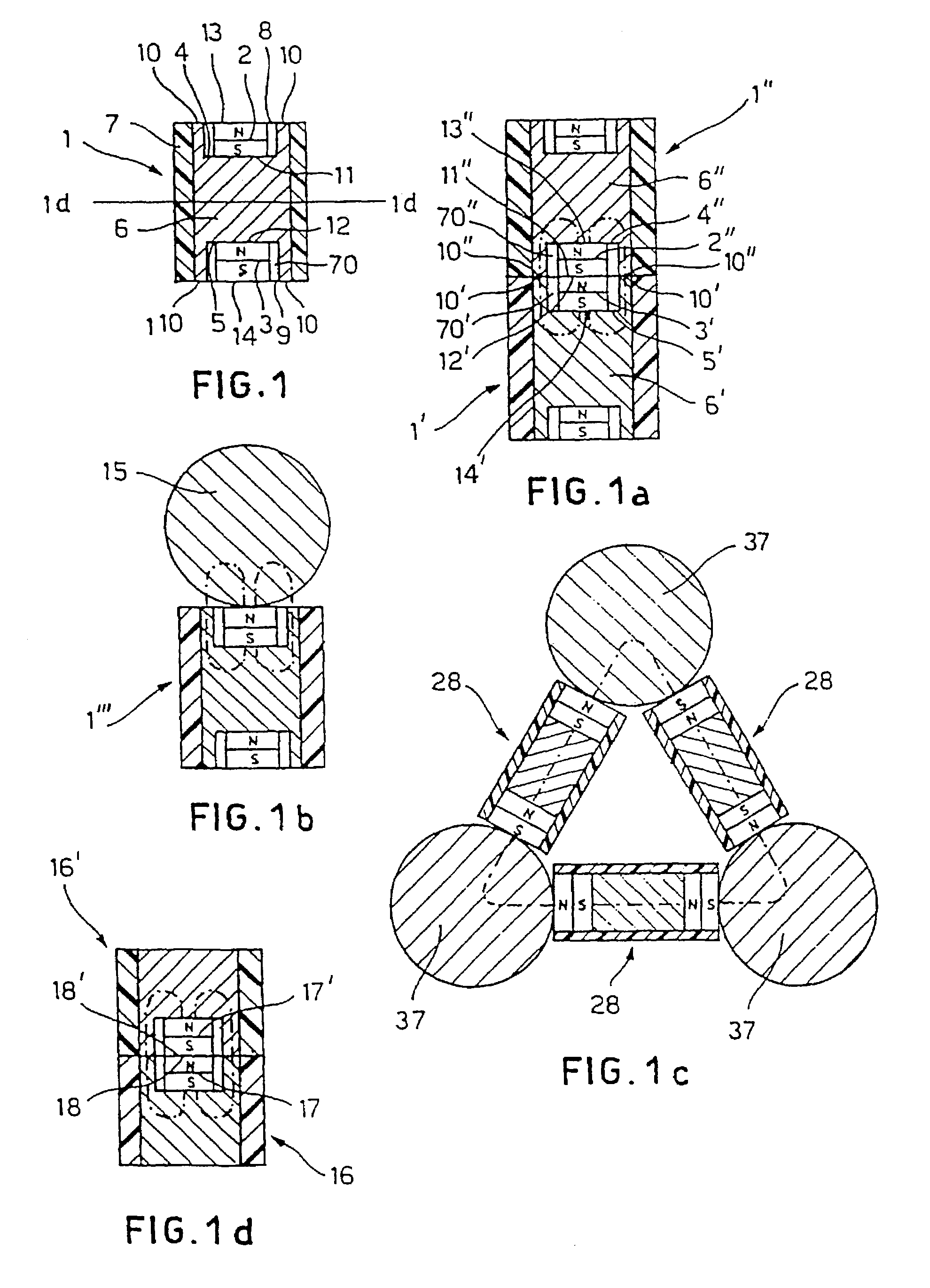
[0032]The permanently magnetic module 1 of FIG. 1 comprises two upper 2 and respectively lower 3 cylindrical magnetic elements housed inside slots 4 and respectively 5, formed on the opposite bases of a cylindrical ferromagnetic yoke 6. The slots 4 and 5 are also cylindrical but more extended radially than the magnets 2 and 3 in order to define an interspace 70 between the lateral walls of the upper and lower magnets 2 and 3 respectively and the lateral walls of the corresponding slots 4 and 5. The magnets 2 and 3 have axes of magnetic polarisation parallel to the axis of the yoke 6 and are connected in series via the ferromagnetic yoke 6.

[0033]The core formed by the two magnets 2 and 3 and by the ferromagnetic yoke 6 is integrated in a non-magnetic matrix 7 with a hollow cylinder shape and open at the bases to leave uncovered the polar surfaces 13 and 14 of the magnets 2 and 3 and the upper 10 and lower 110 edges of the ferromagnetic yoke 6 for the connection to other modules.

[0034...


PUM


Abstract

A module (1, 16, 19, 28, 50, 52, 54, 100) for the creation of assemblies comprising at least one active magnetic element of attraction (2, 3, 17, 20, 33, 34, 42, 47, 48) and at least one ferromagnetic element (6, 21, 22, 30, 40, 44) suitable for defining areas (13, 14, 35, 36, 88, 90, 80, 82, 110, 10, 250, 260, 92, 94) for connection to other modules, with which it is possible to create an assembly of modules (1, 16, 19, 28, 50, 52, 54, 100, 37, 15) which provides a magnetic circuit which closes totally or at least partially via the ferromagnetic elements present (6, 21, 22, 30, 40, 44, 55, 104, 37, 15).

Description

[0001]This application is a division of application Ser. No. 09 / 700,761, filed on Nov. 20, 2000 now U.S. Pat. No. 6,566,992, application Ser. No. 09 / 700,761 is the national phase of PCT International Application No. PCT / EP99 / 02040 filed on Mar. 24, 1999 under 35 U.S.C. § 371. The entire contents of each of the above-identified applications are hereby incorporated by reference.BACKGROUND OF THE INVENTION[0002]1. Summary of the Invention[0003]The present invention relates to modules which can be coupled to form assemblies which can be used in various technical fields, for example for creating assemblies for games or education, furnishing accessories in the form of ornaments, models of molecule aggregates, patterns, stages, stage-set structures and many other uses.[0004]2. Description of the Related Art[0005]Modules in a permanently magnetic material are known and used for single applications and not for the assembly of many modules. These permanent magnet modules are used for example ...

Claims


Application Information

Patent Timeline
IPC IPC(8): H01F7/02A63H33/10G09B1/38G09B23/04G09B23/26
CPCG09B1/38H01F7/0231G09B23/26G09B23/04A63H33/046
Inventor VICENTELLI, CLAUDIO
Owner VICENTELLI CLAUDIO
Why Eureka
Try Eureka