Journal and Thrust Gas Bearing

Active Publication Date: 2021-06-03
ELLIOTT CO
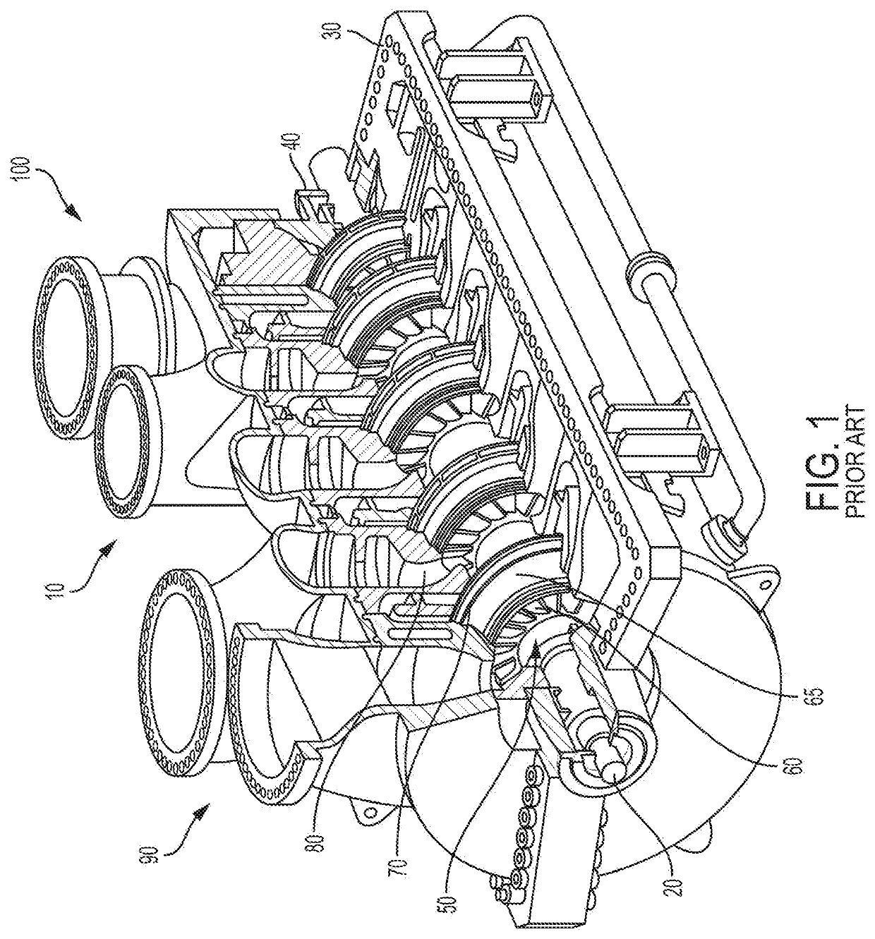
View PDF0 Cites 0 Cited by
  • Summary
  • Abstract
  • Description
  • Claims
  • Application Information

AI Technical Summary

Benefits of technology

[0013]According to an example of the present disclosure, improved bearings for use in turbomachines are provided. The improved bearings may be configured to reduce air leakage through the bearing

Problems solved by technology

Combining the thrust and journal bearings in this manner

Method used


Image

  • Journal and Thrust Gas Bearing
  • Journal and Thrust Gas Bearing
  • Journal and Thrust Gas Bearing

Examples


Example

[0065]For purposes of the description hereinafter, the terms “end”, “upper”, “lower”, “right”, “left”, “vertical”, “horizontal”, “top”, “bottom”, “lateral”, “longitudinal”, and derivatives thereof shall relate to the invention as it is oriented in the drawing figures. However, it is to be understood that the invention may assume various alternative variations and step sequences, except where expressly specified to the contrary. It is also to be understood that the specific devices and processes illustrated in the attached drawings and described in the following specification are simply exemplary embodiments or aspects of the invention. Hence, specific dimensions and other physical characteristics related to the embodiments or aspects disclosed herein are not to be considered as limiting.

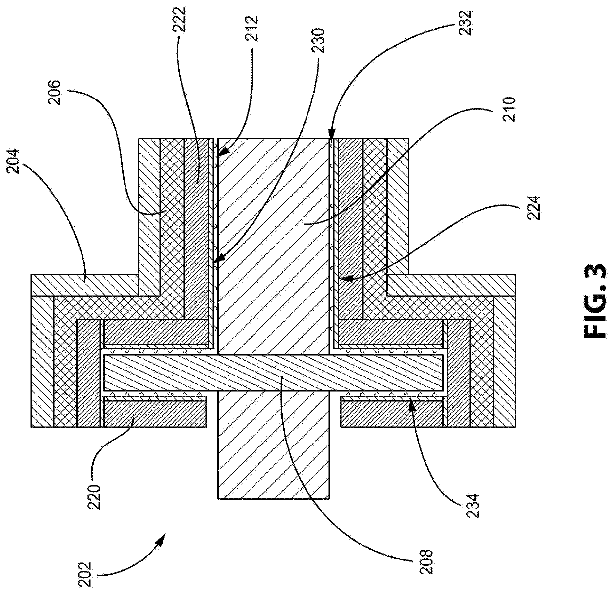
[0066]With reference to FIGS. 3 and 4, a bearing 202 is shown in accordance with an example of the present disclosure. The bearing 202 includes a journal bearing 222 and a thrust gas bearing 220. A p...


PUM


Abstract

A bearing includes a thrust gas bearing attached to a journal bearing and two or more converging-diverging orifices defined in a surface of at least one of the thrust gas bearing and the journal bearing. The converging-diverging orifices supply at least one pressurized gas to an interior of the bearing. Hydrodynamic lifting grooves are provided on the faces of the thrust gas bearing and the journal bearing and provide improved load capacity and sealing capabilities. Control over the ratios of the pressurized gases provides for additional sealing capabilities and reduced leakage. A metal mesh damper provides increased damping of the gas bearing.

Description

CROSS REFERENCE TO RELATED APPLICATIONS[0001]The present application claims priority to U.S. Provisional Patent Application No. 62 / 942,817, filed on Dec. 3, 2019, which is incorporated herein by reference in its entirety.BACKGROUND OF THE INVENTIONField of the Invention[0002]The present disclosure relates generally to thrust and journal bearings, and more particularly, to a joined journal and thrust gas bearing with converging-diverging orifice geometries, as well as a turbomachine that operates with the bearing.Description of Related Art[0003]Turbomachines, such as centrifugal flow compressors, axial flow compressors, and turbines, may be utilized in various industries. Centrifugal flow compressors and turbines, in particular, have a widespread use in power stations, jet engine applications, gas turbines, and automotive applications. Centrifugal flow compressors and turbines are also commonly used in large-scale industrial applications, such as air separation plants and hot gas exp...

Claims


Application Information

Patent Timeline
IPC IPC(8): F16C17/04F01D25/16F04D29/057
CPCF16C17/045F01D25/162F04D29/057F05D2220/30F05D2240/52F05D2240/53F16C2360/23F01D25/22F16C32/0696F16C32/0622F16C2360/00F05D2250/323F05D2250/324F05D2300/6012F05D2300/613F05D2300/601F01D25/164F01D11/04F01D25/168F04D17/10F04D17/122F04D19/02F04D19/00F04D29/0513
Inventor HANTZ, BRIAN DOUGLASBRUN, KLAUSLI, WEIPETTINATO, BRIAN CHRISTOPHERTHORAT, MANISH RAMBHAUWANG, QINGYU
Owner ELLIOTT CO
Why Eureka
Try Eureka