
Receiving system for digital broadcasting, data transmitting method in digital broadcasting receiving system, and receiving apparatus for digital broadcasting

a technology of receiving system and receiving apparatus, applied in the field of receiving system for digital broadcasting, data transmitting method of digital broadcasting receiving system, and receiving apparatus for digital broadcasting, can solve the problems of inability to decode, difficulty in allocating node number and transmitting data, and inability to cope with a new undefined equipment cas

Inactive Publication Date: 2006-05-02
SONY CORP
View PDF11 Cites 22 Cited by
  • Summary
  • Abstract
  • Description
  • Claims
  • Application Information

AI Technical Summary

Benefits of technology

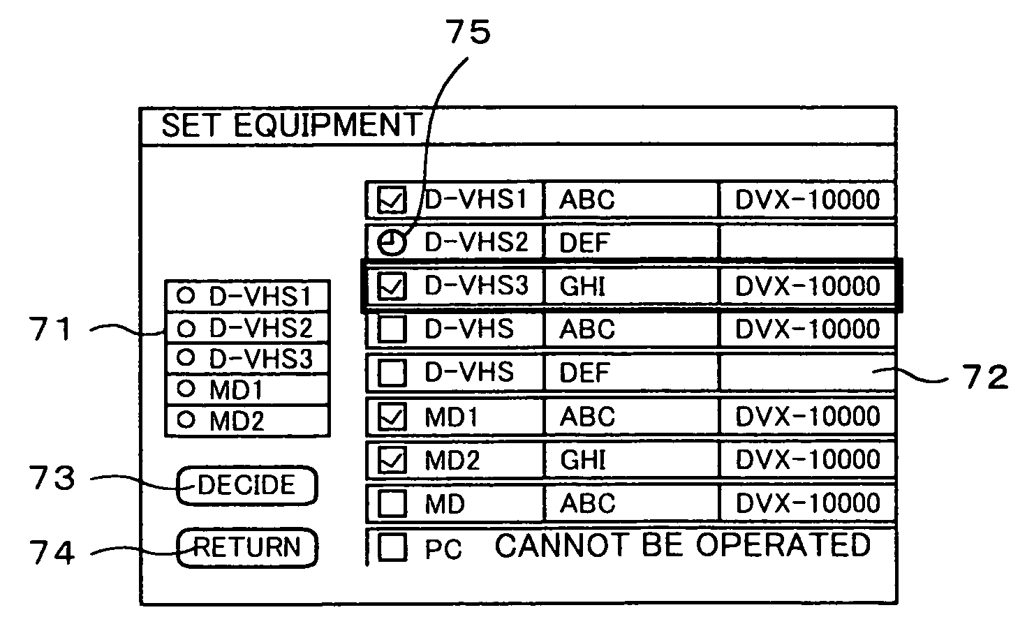
[0016]According to the invention, the node No. “63” of IEEE1394 can be set to the broadcasting channel. Since data is transmitted to all equipment by the broadcasting channel, data can be also transferred to undefined equipment. In the broadcasting channel, since the transport stream of MPEG and the PCM audio can be selected, when the undefined equipment is connected to the IEEE1394 bus, it is possible to cope with any equipment.

Problems solved by technology

In the case where such new equipment is added to the system, since equipment cannot be specified, it is difficult to allocate the node number and transmit data.
However, in digital audio equipment such as an MD recording / reproducing apparatus, even if the MPEG transport stream is received, it cannot be decoded.
As mentioned above, even if the broadcasting channel can be used, if the kind of data which is used in the broadcasting channel cannot be set, it is impossible to cope with a case where new undefined equipment is connected.

Method used


Image

  • Receiving system for digital broadcasting, data transmitting method in digital broadcasting receiving system, and receiving apparatus for digital broadcasting
  • Receiving system for digital broadcasting, data transmitting method in digital broadcasting receiving system, and receiving apparatus for digital broadcasting
  • Receiving system for digital broadcasting, data transmitting method in digital broadcasting receiving system, and receiving apparatus for digital broadcasting

Examples


Embodiment Construction

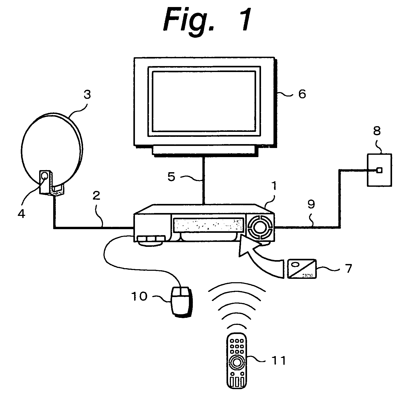
[0028]An embodiment of the invention will now be described hereinbelow with reference to the drawings. In FIG. 1, reference numeral 1 denotes an IRD. The IRD 1 decodes a reception signal of a digital satellite broadcasting and forms a video signal and an audio signal of, for example, the NTSC system. An antenna terminal of the IRD 1 is connected through a cable 2 to a low-noise converter 4 attached to a parabolic antenna 3. A radio wave from a satellite is transmitted by, for example, a band of 12 GHz. The radio wave from the satellite is received by the parabolic antenna 3 and converted into a signal of, for example, a band of 1 GHz by the low-noise converter 4 attached to the parabolic antenna 3.

[0029]An output of the low-noise converter 4 is supplied to the antenna terminal of the IRD 1 through the cable 2. In the IRD 1, a signal of a desired carrier wave is selected from the reception signal and a transport stream of MPEG2 is demodulated. A video packet and an audio packet of a ...


PUM


Abstract

When data is transmitted by using a broadcasting channel of an IEEE1394 interface, it is enabled to cope with a case where undefined equipment is connected to an IEEE1394 bus. The IEEE1394 interface is provided for an IRD, thereby enabling the IRD and equipment such as digital VCR, MD player / recorder, or the like to be connected. A node No. “63” of IEEE1394 is set to the broadcasting channel. Data is transmitted to all equipment connected to the IEEE1394 bus by the broadcasting channel. In the broadcasting channel, a picture plane for selecting a transport stream of MPEG and PCM audio data is displayed, and the data which is transmitted by the broadcasting channel can be selected in accordance with the transport stream of MPEG and the PCM audio data. Thus, when undefined equipment is connected to the IEEE1394 bus, it is possible to cope with any equipment.

Description

BACKGROUND OF THE INVENTION[0001]1. Field of the Invention[0002]The invention relates to a receiving system for a digital broadcasting for receiving a signal in which, for example, video data and audio data are broadcasted by a transport stream of an MPEG (Moving Picture Experts Group) 2 system and transmitting the transport stream to digital signal processing equipment through an interface of IEEE (Institute of Electrical Electronic Engineers) 1394. The invention also relates to a data transmitting method in such a digital broadcasting receiving system and a receiving apparatus for a digital broadcasting which is used for such a system.[0003]2. Description of the Related Art[0004]In recent years, IEEE1394 has been started to spread as an interface to transfer video data and audio data between digital video equipment and digital audio equipment at a high speed. In IEEE1394, an isochronous transfer mode and an asynchronous transfer mode are supported. The isochronous transfer mode is...

Claims


Application Information

Patent Timeline
Patent Type & Authority Patents(United States)
IPC IPC(8): G06F3/00G06F13/00H04N5/445H04L12/28H04L12/40H04N5/44H04N5/455H04N5/60H04N7/015H04N7/12H04N7/20H04N19/00H04N19/44H04N21/436H04N21/442
CPCH04L12/2805H04L12/282H04L12/40052H04L12/40078H04N21/47H04N5/445H04N7/163H04N21/43615H04N21/43632H04L12/40117H04L12/2807H04L2012/2849H04N7/12
Inventor INOUE, HAJIMEWAKAHARA, TATSUYAMURAYAMA, NAOKIMIZUTANI, MASAO
Owner SONY CORP
Learn More