Phase change memory apparatus

a phase change and memory technology, applied in the field of memory devices, can solve problems such as malfunctions of phase change memory apparatuses, problems in reducing the sensing window,

Active Publication Date: 2010-11-18
SK HYNIX INC
View PDF5 Cites 96 Cited by
  • Summary
  • Abstract
  • Description
  • Claims
  • Application Information

AI Technical Summary

Problems solved by technology

However, the input signal ‘SAI’ of the sense amplifier can adversely influenced by fluctuation in the process/voltage/temperature (PVT), which causes probl

Method used


Image

  • Phase change memory apparatus
  • Phase change memory apparatus
  • Phase change memory apparatus

Examples


Embodiment Construction

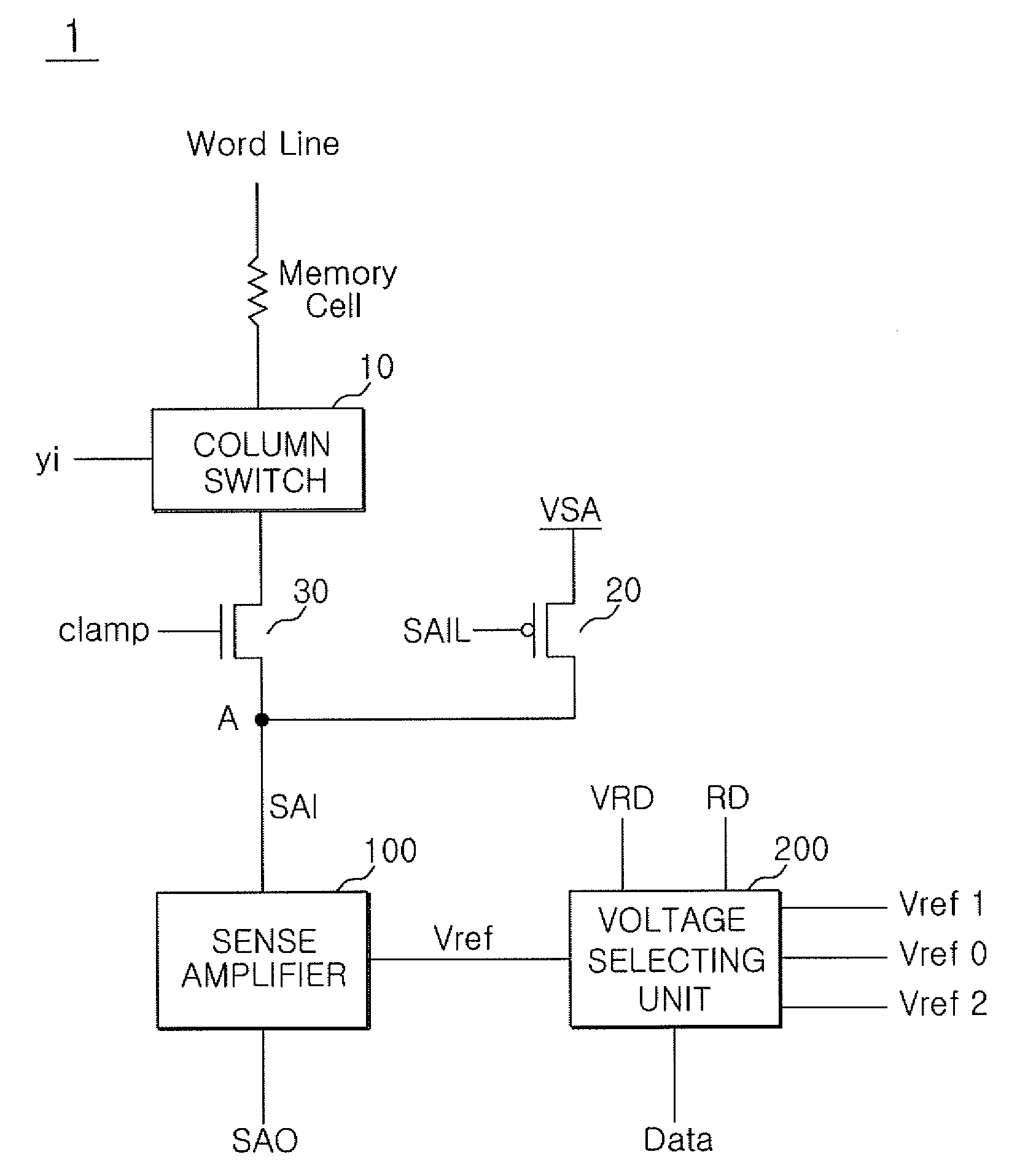
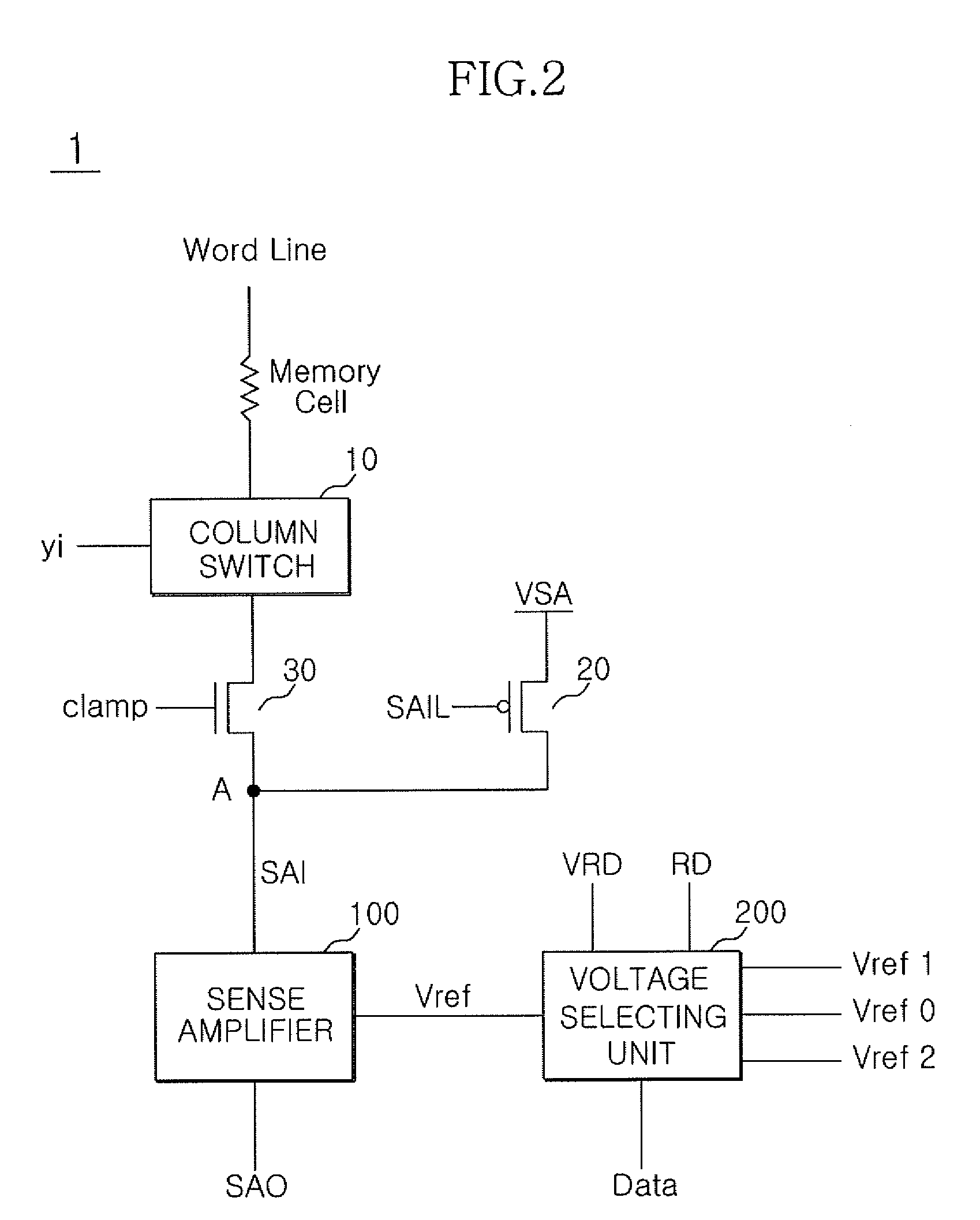
[0020]FIG. 2 is a diagram schematically showing a configuration of a phase change memory apparatus according to the embodiment.

[0021]In FIG. 2, a phase change memory apparatus 1 according to the embodiment can include a memory cell, a column switch 10, a bias transistor 20, a clamping transistor 30, a sense amplifier 100, and a voltage selecting unit 200.

[0022]The memory cell stores data and is operated by being connected to a word line. The column switch 10 is turned-on in response to a column selection signal ‘yi’ that is enabled to select a column in accordance with a column address.

[0023]The bias transistor 20 applies a power supply voltage ‘VSA’ to a common node ‘A’ in response to a biasing signal ‘SAIL’ in order to sense the data of the memory cell.

[0024]The clamping transistor 30 performs clamping within a voltage range, suitable to read the data of the memory cell, in response to the clamping signal ‘clamp’. Specifically, the clamping transistor 30 performs clamping to a pre...


PUM


Abstract

A phase change memory apparatus is presented. The phase change memory apparatus includes a phase change memory cell, a sense amplifier, and a voltage selecting unit. The sense amplifier is configured to differentially amplify a current that through the memory cell and a comparison voltage. The voltage selecting unit is configured to provide a reference voltage as the comparison voltage when performing a normal read function and to selectively provide either a first voltage level or a second voltage level as the comparison voltage in accordance with data when performing a verify read function.

Description

CROSS-REFERENCES TO RELATED PATENT APPLICATION[0001]The present application claims priority under 35 U.S.C 119(a) to Korean Application No. 10-2009-0042605, filed on May 15, 2009, in the Korean Intellectual Property Office, which is incorporated herein by reference in its entirety as set forth in full.BACKGROUND[0002]1. Technical Field[0003]The present invention relates to a memory apparatus, and more particularly, to a phase change memory apparatus.[0004]2. Related Art[0005]Generally, a phase change memory apparatus performs a write verify function that verifies whether or not data has been correctly stored in a memory cell. The write verify function is usually performed as follows. First, logic-high data or logic-low data are written in the memory cell and the data stored in the memory cell is read by a verify read function. When the written data and the read data do not conform to each other, then data are rewritten in the memory cell. Subsequently another verify read function, w...

Claims


Application Information

Patent Timeline
IPC IPC(8): G11C11/00G11C7/02
CPCG11C11/5678G11C13/0064G11C13/0004G11C13/02G11C16/34
Inventor PARK, KYOUNG WOOK
Owner SK HYNIX INC
Why Eureka
Try Eureka