
Braking control system for a washing machine

a control system and washing machine technology, applied in other washing machines, spin-dryers, textiles and papermaking, etc., can solve the problems of excessive vibration of the machine and similar vibration problems of the machine, and achieve the effect of effective braking, reducing the amount of time, and substantially eliminating the effects of high vibration due to unbalanced load

Inactive Publication Date: 2006-05-09
MAYTAG
View PDF44 Cites 23 Cited by
  • Summary
  • Abstract
  • Description
  • Claims
  • Application Information

AI Technical Summary

Benefits of technology

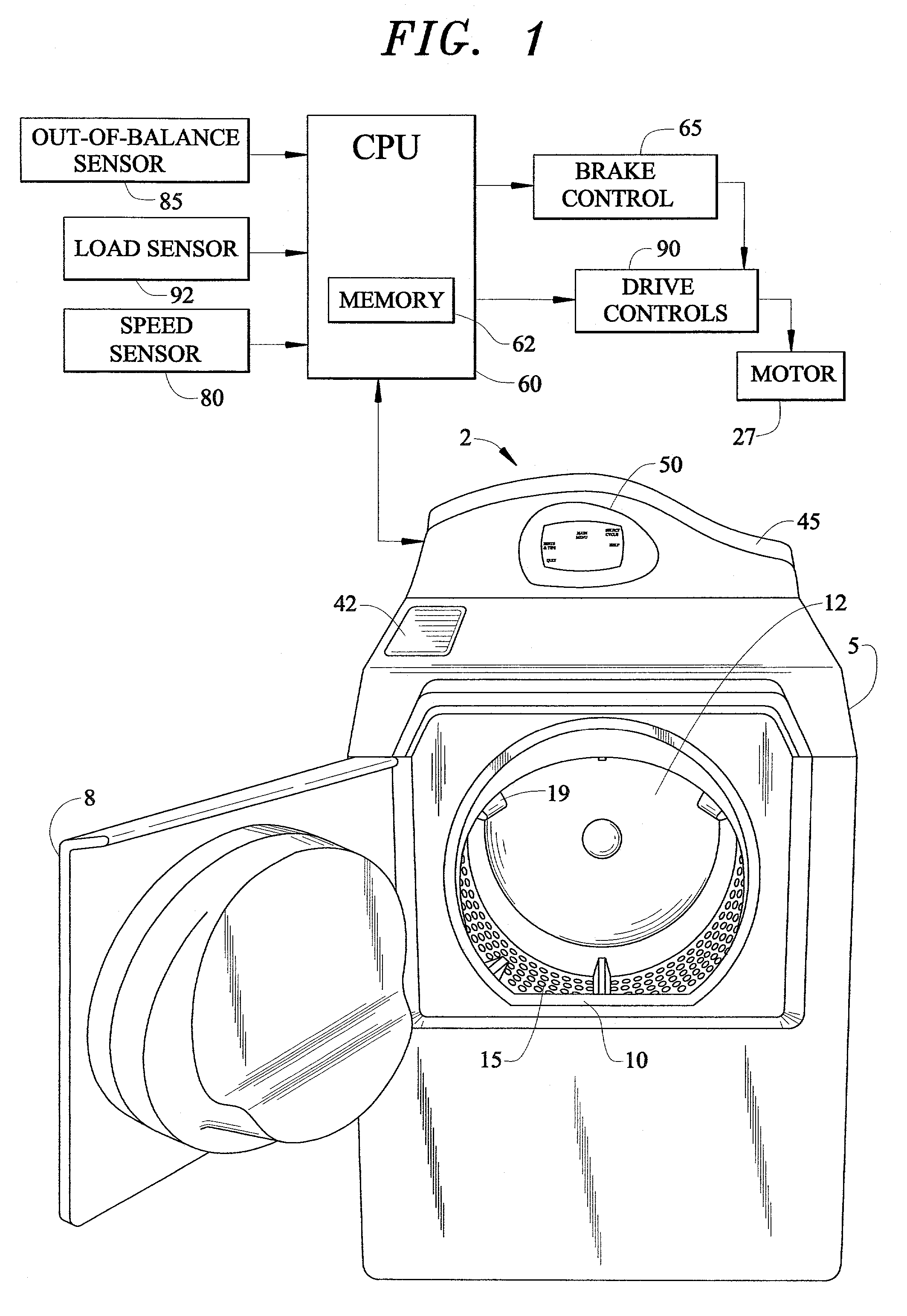
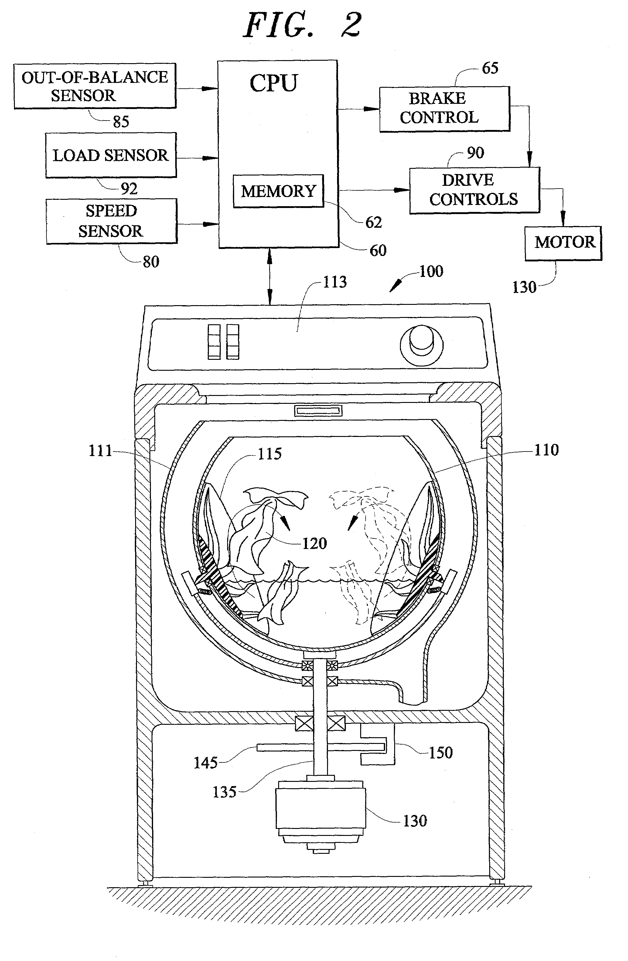
[0006]The present invention is directed to a system and method for effectively braking an inner tub or spinner of a washing machine following an extraction phase of a spin cycle to reduce the amount of time the inner tub is near the resonant frequency of the machine. Experience has shown that an out-of-balance condition will occur within a discrete or critical speed band during deceleration (assuming a generally consistent load size). Therefore, if the inner tub is caused to rapidly pass through the critical speed band during braking, the effects of high vibrations due to an unbalanced load is substantially eliminated. To this end, in accordance with the invention, a control system is incorporated into the washing machine to rapidly decelerate the inner tub through the critical speed band, preferably by applying a short burst of braking force, e.g., a pulsed braking force, to reduce the impact on electronic control components.
[0007]In accordance with the invention, an out-of-balance sensor is provided to sense the onset of an unbalance condition. The sensor will signal a controller which will operate a brake to rapidly decelerate the inner tub. More particularly, in one preferred embodiment, the controller is configured to intermittently operate the brake to slow the inner tub through the critical speed band such that component life can be extended. In another preferred embodiment, the brake control of the present invention is incorporated into systems having a mechanical brake. As mechanical braking systems are exposed to potential damage when subjected to excessive or extreme out-of-balance conditions, the present invention preferably provides for intermittent operation of the mechanical brake to aid in handling unbalanced loads.
[0008]In a still further preferred form of the embodiment, the control system of the present invention will “learn” the location of the critical speed band during a spin cycle in which an out-of-balance condition is likely to occur for any given load size. The location will be stored in a memory including a “look-up” table such that the control will activate the brake over a known discrete speed band in order to reduce the impact of an out-of-balance condition.

Problems solved by technology

During the extraction phase of the spin cycle, the uneven distribution of the clothes results in an out-of-balance condition which causes excessive vibration of the machine.
However, during the deceleration phase, an out-of-balance condition can cause the machine to experience similar vibration problems as during the extraction phase of the spin cycle.

Method used


Image

  • Braking control system for a washing machine
  • Braking control system for a washing machine
  • Braking control system for a washing machine

Examples


Embodiment Construction

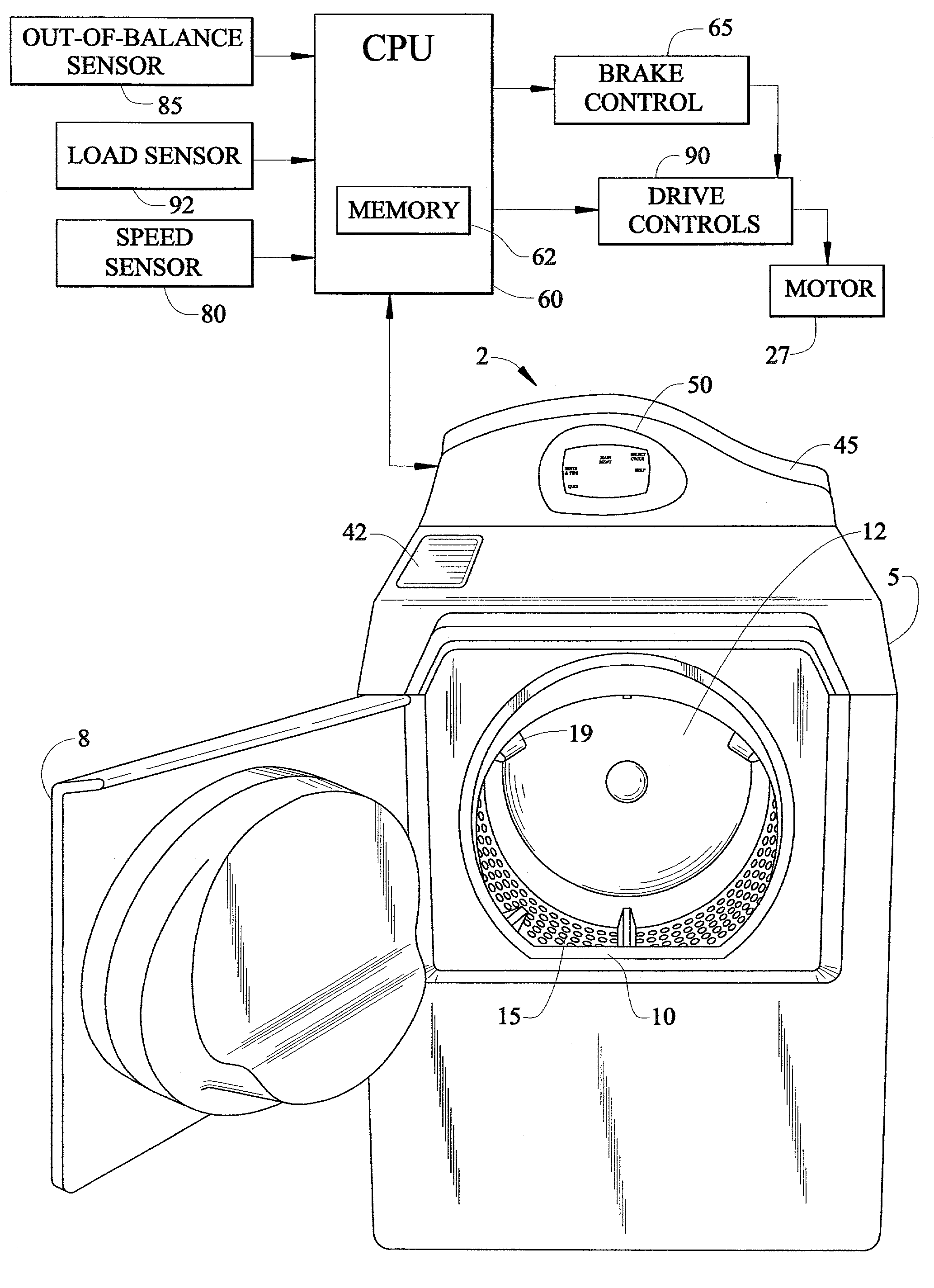
[0012]With initial reference to FIG. 1, an automatic horizontal axis washing machine incorporating the braking control system of the present invention is generally indicated at 2. In a manner known in the art, washing machine 2 is adapted to be front loaded with articles of clothing to be laundered through a tumble-type washing operation. As shown, automatic washing machine 2 incorporates an outer cabinet shell 5 provided with a front door 8 adapted to extend across an access opening 10. Front door 8 can be selectively pivoted to provide access to an inner tub or spinner 12 that constitutes a washing basket within which articles of clothing are laundered.

[0013]As is known in the art, inner tub 12 is formed with a plurality of holes 15 and multiple, radially inwardly projecting fins or blades 19 are fixedly secured to inner tub 12. Inner tub 12 is mounted for rotation within an outer tub (not shown) which, in turn, is supported through a suspension mechanism (also not shown) within c...


PUM


Abstract

An inner tub of a washing machine is rapidly braked during a portion of a deceleration phase following an extraction phase of an overall spin cycle. A controller establishes the braking operation over a critical speed band or resonant frequency zone during which excessive vibrations would be developed. The critical speed band is preferably determined based on one or more signals received from speed, load, and / or out-of-balance sensors.

Description

BACKGROUND OF INVENTION[0001]1. Field of Invention[0002]The present invention pertains to the art of washing machines, and more particularly, to a control system for braking an inner tub of a washing machine through a critical speed range within which an out-of-balance condition could occur, such that the washing machine is not exposed to high vibration levels.[0003]2. Discussion of Prior Art[0004]Typical washing machines perform a wash cycle by agitating or tumbling a load of clothes bathed in a water or water / detergent solution within an inner tub. After the wash cycle has completed, a spin cycle, including an extraction phase and a deceleration phase, is required. Most machines perform this cycle by spinning the inner tub at a high rate such that centrifugal forces cause the water or water / detergent solution to separate from the clothes. After a predetermined period has elapsed, drive to the inner tub is disrupted whereby the inner tub is slowly brought to a stop.[0005]It is well...

Claims


Application Information

Patent Timeline
Patent Type & Authority Patents(United States)
IPC IPC(8): D06F33/02D06F33/48D06F34/16D06F37/20
CPCD06F37/203D06F2204/065D06F34/16D06F2105/48D06F33/48D06F2103/26D06F37/42
Inventor SEARS, JEFFREY L.
Owner MAYTAG
Learn More