Handle for tooth cleaning member

Inactive Publication Date: 2006-05-09
DR FRESH LLC
View PDF10 Cites 51 Cited by
  • Summary
  • Abstract
  • Description
  • Claims
  • Application Information

AI Technical Summary

Benefits of technology

[0037]With such a structure, the user can easily enter the tooth cleaning member at the distal end of the neck portion and the neck portion into his mouth.
[0038]In the handle for a tooth cleaning member of the present invention, the pressed portion has a low-rigidity par

Problems solved by technology

It is difficult for such a brush to contact the backside of teeth or between teeth at proper angles.
Furthermore, the toothbrush cannot sufficiently match up to various teeth orientations of users.
In both the cases, whenever he adjusts the angle of the brush head, he must move his thumb so that a grasped part is not stable.
Consequently, the conventional technique has a problem that it is difficult for the user to adjust the force for tooth brushing.
Furthermore, there is an additional problem in the first and second conventional techniques that the construction is complex and costly.
Therefore, the toothbrush has a problem that it is difficult to hold the entire brush on the head uniformly in contact with teeth and gums with the equal pressure.
Furtherm

Method used


Image

  • Handle for tooth cleaning member
  • Handle for tooth cleaning member
  • Handle for tooth cleaning member

Examples


first embodiment

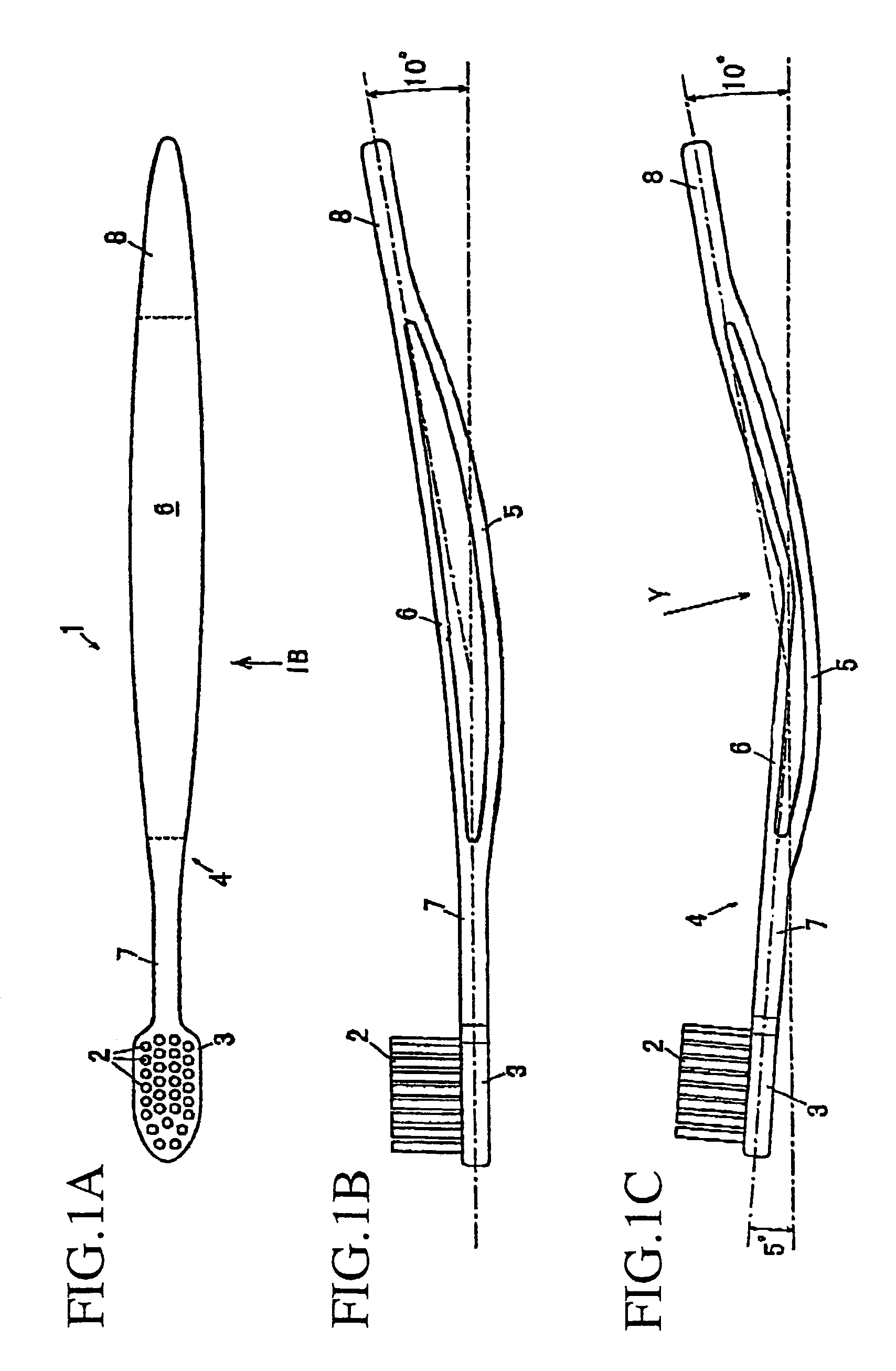
[0108]FIG. 1A is a front view of a toothbrush to which a handle for a tooth cleaning member according to a first embodiment of the present invention is applied. FIG. 1B is a side view in the direction of arrow IB of FIG. 1A while FIG. 1C is a view for illustrating the toothbrush of FIG. 1B in use.

[0109]As shown in FIGS. 1A through 1C, a toothbrush 1 has a head 3 with bristles or a brush (tooth cleaning member) 2 set therein and a handle 4 formed integrally with the head 3. The head 3 and the handle 4 may be integrally molded with each other. Alternatively, the head 3 may be constructed separately form the handle 4, and then coupled with the end of the handle 4.

[0110]The handle 4 can be made of a material that is the same as that of conventional toothbrush handles. Additionally, stainless steel and the like may be used as the material of the handle 4.

[0111]The handle 4 comprises a curvilinear support portion 5 made of an elastic material, and a pressed portion 6 made of an elastic ma...

second embodiment

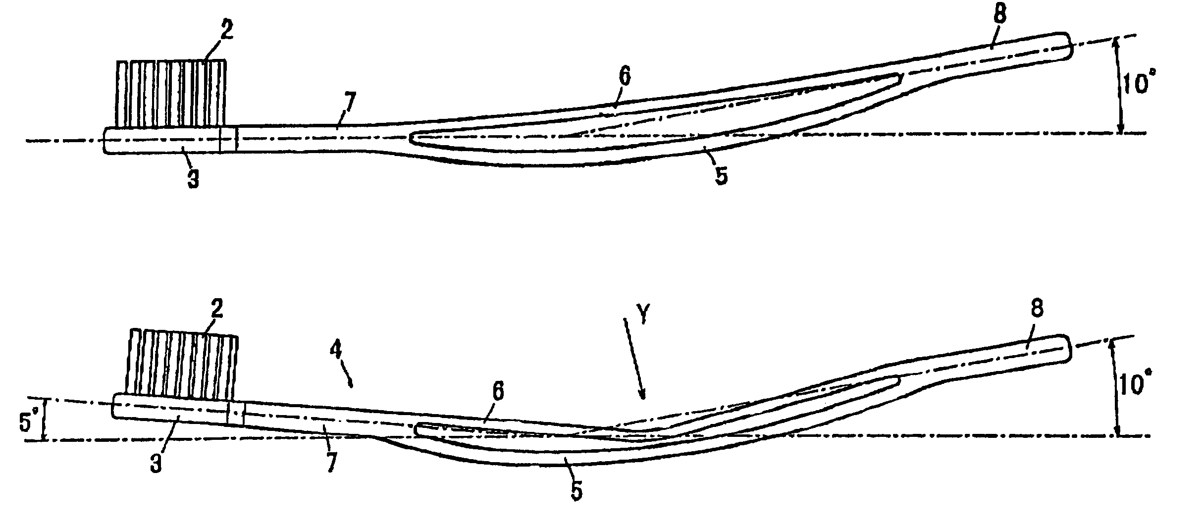
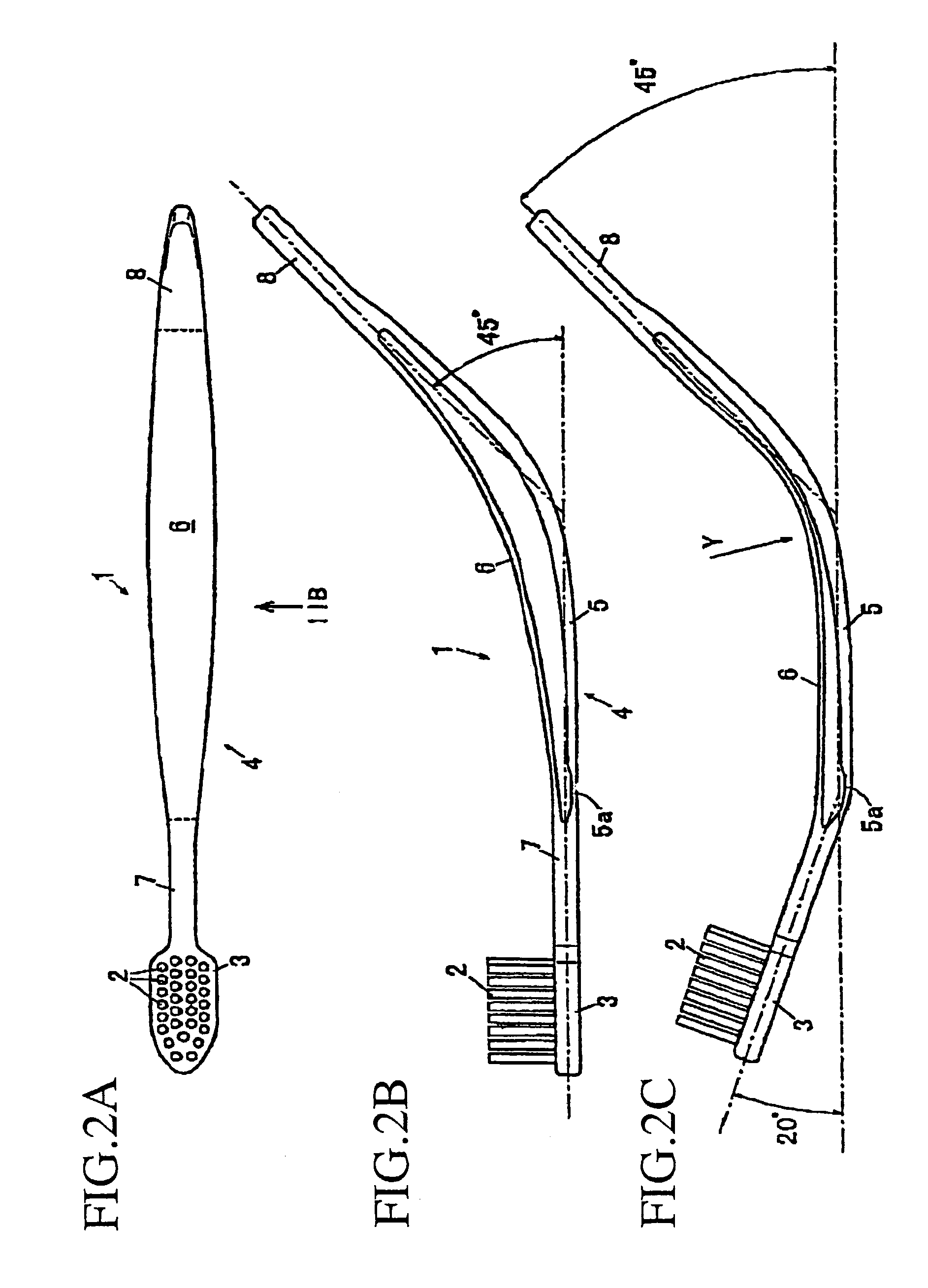
[0120]FIG. 2A is a front view of a toothbrush according to a second embodiment of the present invention. FIG. 2B is a side view in the direction of arrow IIB of FIG. 2A while FIG. 2C is a view for illustrating the toothbrush of FIG. 2B in use. In these drawings, the same reference signs as are used above are also used for identifying elements illustrated already in FIGS. 1A through 1C to avoid redundant explanation.

[0121]The toothbrush 1 of the second embodiment is constructed differently from the first embodiment in the following respects but similarly to the first embodiment in other respects.

[0122]As shown in FIG. 2B, the angle between the centerline of the brush-side end 7 and the centerline of the proximal end 8 is 45 degrees in the usual state. A thin low-rigidity part 5a is formed at one end of the support portion 5 neighboring on the brush-side end 7 (the end closer to the brush 2). Since the connection between the pressed portion 6 and the brush-side end 7 is closer to the ...

third embodiment

[0127]FIG. 4A is a front view of an interdental brush to which a handle for a tooth cleaning member according to a third embodiment of the present invention is applied.

[0128]FIG. 4B is a side view in the direction of arrow IVB of FIG. 4A while FIG. 4C is a view for illustrating the interdental brush of FIG. 4B in use.

[0129]In these drawings, the same reference signs as are used above are also used for identifying elements illustrated already in FIGS. 1A through 3 to avoid redundant explanation.

[0130]The interdental brush 11 of the third embodiment is constructed differently from the second embodiment in the following respects but similarly to the second embodiment in other respects.

[0131]As shown in FIGS. 4A to 4C, the interdental brush 11 of the third embodiment has the handle 4 which is the same as in the toothbrush 1 of the second embodiment. A head 13 with a hole 13a for receiving a brush body 12 is integrally formed with the distal end of the brush-side end 7 of the handle 4. T...


PUM


Abstract

This invention provides a handle for a tooth cleaning member convenient for use in which the angle of the tooth cleaning member can be easily adjusted for cleaning teeth only by controlling the force for grasping the grip part. The handle comprises a support portion made of an elastic material, and a pressed portion shorter than the support portion. When the pressed portion is pressed against the support portion, the support portion is transformed to increase its curvature.

Description

TECHNICAL FIELD[0001]This invention relates to a handle, grasped by a user's hand, for a tooth cleaning member, e.g., a toothbrush or an interdental brush.BACKGROUND ART[0002]A conventional toothbrush generally has a head and a handle. The handle is formed to be straight or curvilinear and cannot be transformed.[0003]It is difficult for such a brush to contact the backside of teeth or between teeth at proper angles. Furthermore, the toothbrush cannot sufficiently match up to various teeth orientations of users.[0004]In order to solve these problems, handles capable of adjusting the angle of a toothbrush head have been developed, publicly known and disclosed in the following publications.First Conventional Technique Described in JP-A-3(1991)-500494[0005]This publication discloses a handle for a toothbrush where a brush head is rotatably supported in an end of the handle, two parallel handle members are provided in the other end of the handle and the two handle members are coupled by ...

Claims


Application Information

Patent Timeline
IPC IPC(8): A46B5/00A61C15/00A61C17/00
CPCA46B5/0075A46B5/0079A46B2200/1066A46B5/02
Inventor WATANABE, TAKAYUKIMATSUMOTO, NORIOIKEDA, AKINORI
Owner DR FRESH LLC
Why Eureka
Try Eureka