Fan motor suspension mount for a combustion-powered tool

Inactive Publication Date: 2006-05-09
ILLINOIS TOOL WORKS INC
View PDF43 Cites 36 Cited by
  • Summary
  • Abstract
  • Description
  • Claims
  • Application Information

AI Technical Summary

Benefits of technology

[0012]The present invention provides a mount for a fan motor suspension mechanism of a combustion-powered tool. The tool is of the type that generates an upward axial acceleration of the motor upon a combustion in the chamber and a subsequent reciprocal axial acceleration of the motor, where at least one of the accelerations causes the motor to oscillate relative to the tool. The suspension mechanism includes a mount having a inner ring configured to be secured to the motor, an outer ring configured to be secured to a portion of the tool, and a web radially disposed between and connecting the inner and outer ring. The inner ring, outer ring, and web of the mount are a unitary piece.
[0013]Preferably, the web

Problems solved by technology

These reciprocal accelerations cause the fan motor to oscillate with respect to the tool.
The magnitude of these accelerations, if left unmanaged, is detrimental to the life and reliability of the combustion chamber fan motor.
Before such suspension mechanisms, specially designed motors were requ

Method used


Image

  • Fan motor suspension mount for a combustion-powered tool
  • Fan motor suspension mount for a combustion-powered tool
  • Fan motor suspension mount for a combustion-powered tool

Examples


Embodiment Construction

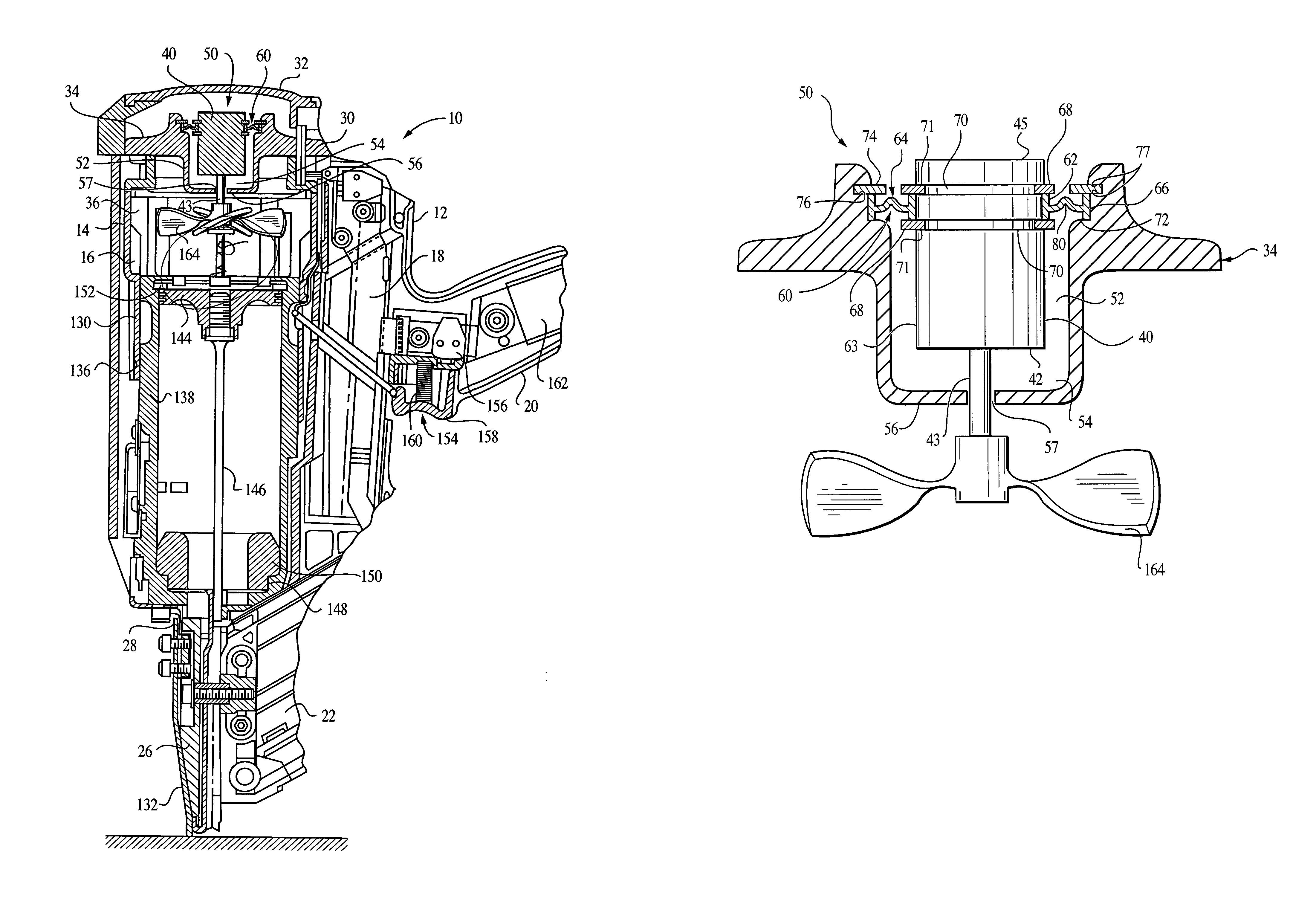
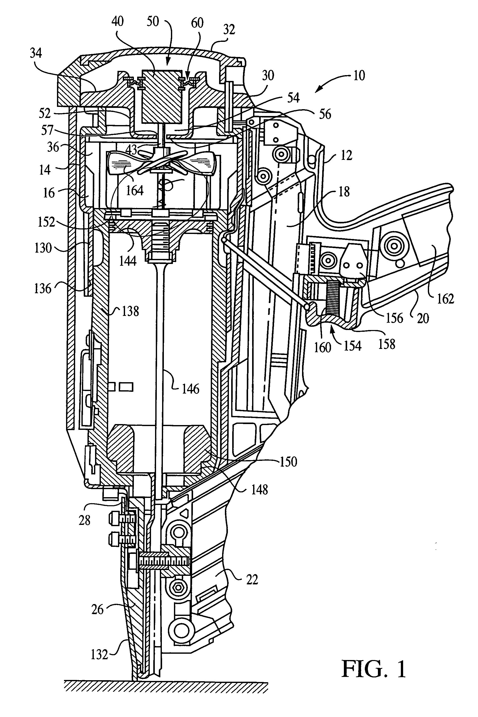
[0022]Referring now to FIG. 1, a combustion-powered tool of the type suitable for use with the present invention is generally designated 10. While one type of combustion-powered tool is depicted here, it is contemplated that other tool configurations and arrangements of components may be provided that are suitable for use with the present suspension. The tool 10 has a housing 12 including a main power source chamber 14 dimensioned to enclose a self-contained internal combustion power source 16, a fuel cell chamber 18 generally parallel with and adjacent to the main chamber 14, and a handle portion 20 extending from one side of the fuel cell chamber and opposite the main chamber.

[0023]In addition, a fastener magazine 22 is positioned to extend generally parallel to the handle portion 20 from an engagement point with a nosepiece 26 depending from a lower end 28 of the main chamber 14. A battery (not shown) is provided for supplying electrical power to the tool 10, and is releasably ho...


PUM

PropertyMeasurementUnit
Waveaaaaaaaaaa
Thermoplasticityaaaaaaaaaa

Abstract

A motor mount for suspending a fan motor in a combustion-powered tool includes an inner ring for securing to the motor, an outer ring that is secured to a portion of the tool, and a web portion disposed between and connecting the inner ring and outer ring. The inner ring, outer ring, and web portion are formed as a unitary piece. Preferably, the mount is formed of a thermoplastic polyester elastomer.

Description

BACKGROUND OF THE INVENTION[0001]The present invention relates generally to improvements in portable, combustion-powered fastener driving tools, and more particularly to a mount for a combustion chamber fan motor.[0002]Portable, combustion-powered fastener driving tools are used for driving fasteners into workpieces. Exemplary embodiments of fastener driving tools are described in U.S. Pat. Nos. 4,522,162; 4,483,473; 4,483,474; 4,403,722; 5,197,646; 5,263,439; and Re. 32,452, all of which are incorporated by reference herein. Particular embodiments of fastener driving tools are sold, for example, by Illinois Tool Works of Vernon Hills, Ill., under the IMPULSE® and TRIMMASTER® brands.[0003]Tools of the type noted above typically incorporate a generally pistol-shaped tool housing enclosing a small internal combustion engine. The engine is powered by a canister of pressurized fuel gas, also called a fuel cell. A battery-powered electronic power distribution unit produces the spark for ...

Claims


Application Information

Patent Timeline
IPC IPC(8): B25C1/14B25C7/00B25C1/08F16F1/32F16F15/06
CPCB25C1/08F16F15/06F16F1/328F16F15/08F16F1/3732F04D29/668
Inventor TURK, ROBERT L.
Owner ILLINOIS TOOL WORKS INC
Why Eureka
Try Eureka