Joystick controlled scrubber

a scrubber and joystick technology, applied in the direction of motor/generator/converter stopper, dynamo-electric converter control, transportation and packaging, etc., can solve the problems of unsafe condition of machine, inability to travel at high speed and turn the wheel, etc., to improve maneuverability, increase operator visibility, and improve traction

Active Publication Date: 2006-05-09
NILFISK
View PDF15 Cites 79 Cited by
  • Summary
  • Abstract
  • Description
  • Claims
  • Application Information

AI Technical Summary

Benefits of technology

[0010]These and other advantageous features of the present invention will be in part apparent and in part pointed out herein below. The present invention provides a solution to many of the problems outlined above that are encountered with floor maintenance vehicles. It is an object of this invention to provide a steering control system that increases the operators visibility around the periphery of the vehicle. This is accomplished by replacing the typical steering wheel system with a joystick system. It is another object of the invention to integrate the benefits of transaxle drive system with a front wheel steering system, while maintaining safety, maneuverability, and traction. This is accomplished by the joystick control system. It is yet another object of the present invention to integrate and coordinate the speed range level with the steering angle as accomplished by the joystick control system.
[0011]Using two integrated controllers, one for steering and one for traverse, the present invention utilizes a control system that is tied together via the joystick control system. The present invention specifically creates a relationship between traveling speed and turn angle by using two different controllers and a joystick control system that integrates the two. This system makes it impossible to travel at high speed and turn the wheel to its sharpest turning point, placing the machine in an unsafe condition.
[0012]The present invention utilizes a transaxle for a drive system and a powered “steerable” system to control the front wheel for steering purposes. The present invention incorporates a transaxle because it improves traction over a front-mounted single motor drive wheel. Traditionally rear wheel drive units suffered in the area of maneuverability. However in the present design since the operator can only make the machine go very slowly at the maximum turn angle the operator can direct the machine to turn sharper thus improving the overall maneuverability. In the present design with the front wheel turned at maximum angle the operator can only supply a very small amount of forward speed thus allowing the front wheel to maintain traction and turn very sharply. The machine speed and turn angles are tied together in the present invention and prevents the operator from causing the unsafe conditions mentioned earlier.
[0013]The present invention combines things in a way that incorporates the best of all worlds. The present invention provides improved visibility, maneuverability, operator comfort, traction and control. The present invention provides an ideal system for a floor maintenance vehicle, particularly for a scrubber. Although it may be easier to do things like a mobility scooter or other similar device, however it would not drive as smoothly or feel as natural. Also by referencing machine speed the operator does not get false data or false feedback that could come from relying on the position of the joystick alone.
[0014]The present invention is easy and simple to drive and easy to train new operators. Maintenance and repair is facilitated. The present invention is more conducive for people with disabilities. The present invention incorporates all machine movement control into one device.

Problems solved by technology

This system makes it impossible to travel at high speed and turn the wheel to its sharpest turning point, placing the machine in an unsafe condition.

Method used


Image

  • Joystick controlled scrubber
  • Joystick controlled scrubber
  • Joystick controlled scrubber

Examples


Embodiment Construction

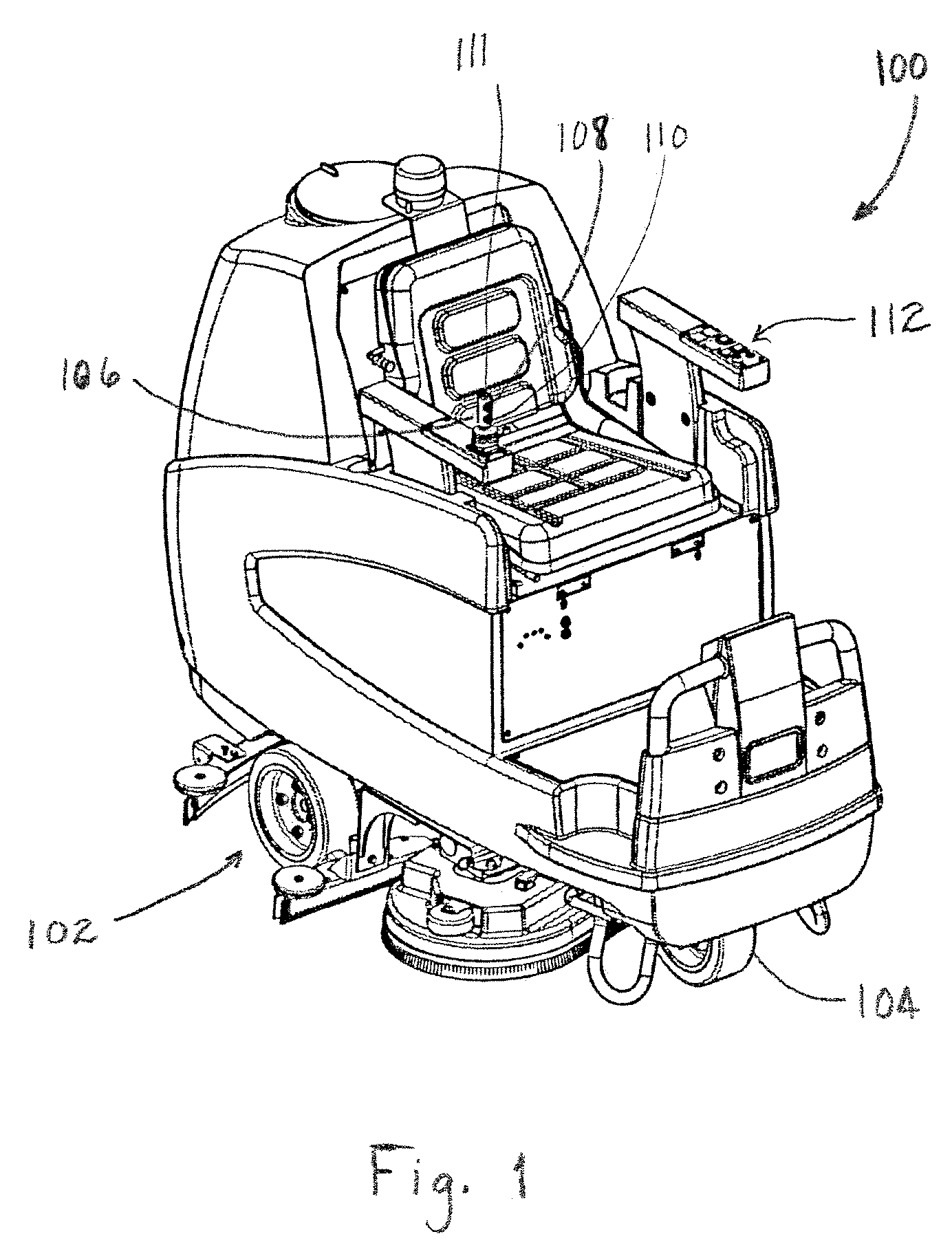
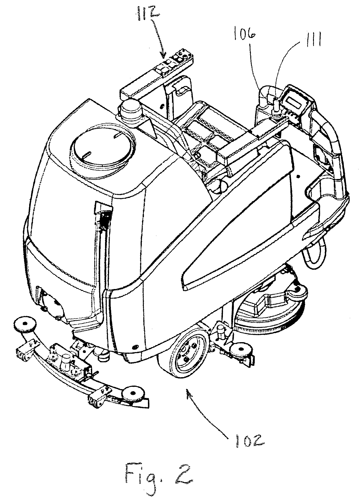
[0022]According to the embodiment(s) of the present invention, various views are illustrated in FIG. 1–3 and like reference numerals are being used consistently throughout to refer to like and corresponding parts of the invention for all of the various views and figures of the drawing. Also, please note that the first digit(s) of the reference number for a given item or part of the invention should correspond to the Fig. No. in which the item or part is first identified.

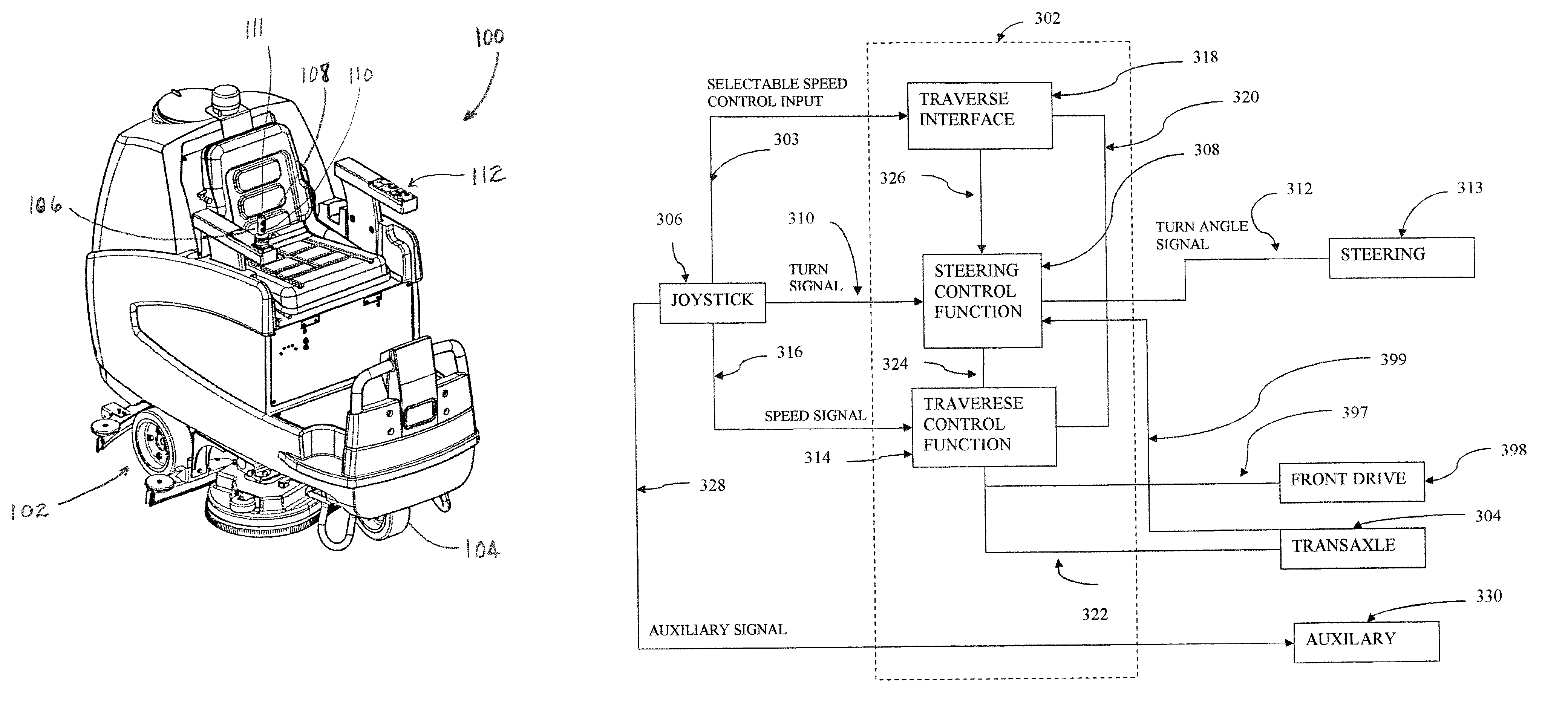
[0023]The details of the invention and various embodiments can be better understood by referring to the figures of the drawing. Referring to FIGS. 1 and 2, one embodiment of the present floor maintenance vehicle 100 invention comprising a transaxle rear drive system 102 and a powered steering system for controlling steering of a front wheel 104; and a joystick control system for providing integrated control of the transaxle rear drive system and the powered steering system by controlling the traverse output of the tr...


PUM


Abstract

An apparatus and method for a floor maintenance vehicle comprises a transaxle rear drive system and a powered front wheel steering system; and a joystick control system providing integrated control of the transaxle rear drive system and the powered steering system by controlling the traverse speed of the transaxle drive with respect to the steering angle such that the sharper the steering angle the lower the maximum traverse speed. A joystick control process for controlling a floor maintenance vehicle comprises receiving a turn signal to a steering control function from a joystick representing an operator desired turn angle, and outputting from the steering control function a turn angle signal; and receiving a speed signal to a traverse control function from a joystick representing an operator desired speed, and receiving the turn angle signal and outputting a transaxle speed control signal based on the speed signal and the turn angle signal.

Description

BACKGROUND OF INVENTION[0001]1. Field of Invention[0002]This invention relates generally to floor maintenance machines and, more particularly, to steering control systems for floor maintenance vehicles.[0003]2. Background Art[0004]There are various configurations of floor maintenance vehicles. Floor maintenance vehicles may perform a variety of floor maintenance functions including vacuuming, sweeping, waxing, buffing, stripping, scrubbing, soft-floor cleaning and sanding, including carpet cleaning. The floor maintenance vehicles utilized in the floor care industry are typically utilized to maintain flooring in large areas. Although these types of vehicles are utilized to maintain large floor areas, it remains essential that the vehicle is highly maneuverable to navigate in tight areas and around obstacles without skipping over portions of the floor. It is also important that the operator of the vehicle has a high level of visibility around the periphery of the vehicle for better na...

Claims


Application Information

Patent Timeline
Patent Type & Authority Patents(United States)
IPC IPC(8): B60W10/04B60W10/20B62D11/00B62D11/02B62D11/24
CPCB62D11/003B62D11/24Y10T477/30Y10T477/10Y10S477/903
Inventor FULGHUM, TRENT A.WHITAKER, EMERT R.
Owner NILFISK
Why Eureka
Try Eureka