Passive safety shield system for injection devices

a shield system and injection device technology, applied in the direction of intravenous devices, infusion needles, other medical devices, etc., can solve the problems of no positive assurance that the end user will properly shield, and no positive assurance that the user will use properly

Inactive Publication Date: 2006-05-09
BECTON DICKINSON & CO
View PDF6 Cites 4 Cited by
  • Summary
  • Abstract
  • Description
  • Claims
  • Application Information

AI Technical Summary

Benefits of technology

[0010]As set forth above, the safety shield system of this invention is passive, but avoids the problems associated with the prior art passive shield systems. The shield system of this invention may be utilized with prefilled syringes of the type described above, but may also be used with other types of injection devices. Premature or inadvertent actuation of the shield system is minimized by an interlock system which allows packing, transportation in bulk and high speed feeding systems in bowls, etc. Further, the needle cover or shield is moved to enclose the needle cannula by release of the plunger, thereby giving the user the option of releasing the needle cover only after complete delivery of the fluid in the syringe and removal of the needle cannula from the patient, while assuring shielding of the syringe needle cannula prior to disposal.
[0011]The disclosed embodiment of the passive shield system of this invention includes four components, namely a generally tubular body having an open proximal end for receipt of a syringe, a generally tubular shield or needle cover telescopically supported by the body and extendable from a retracted position, wherein the syringe needle cannula is exposed, to an extended position enclosing the needle, a spring biasing the shield toward the extended position, and an annular or ring shaped member which interlocks with the body to prevent premature actuation of the shield or needle cover and which actuates the shield upon release of the plunger following complete delivery of the substance in the syringe. In the disclosed embodiment of the shield system of this invention, the needle cover or shield is telescopically received within the body and moveable axially to shield the needle cannula of the syringe as described. The spring and the ring shaped member are received in the open proximal end of the body such that the spring is biased between the ring shaped member and the shield. Prior to receipt of the syringe, the ring shaped member serves as a locking member preventing premature actuation of the shield. The ring shaped member or locking member includes a leg which forms a mechanical interlock with the body. In the disclosed embodiment, the ring shaped member includes two opposed axially extending legs which, in the preferred embodiment, extend proximally, preferably beyond the open end of the body, for actuation of the shield as described below. In the disclosed embodiment, the legs include opposed V-shaped locking surfaces which form a mechanical interlock with an opposed surface of the body adjacent the open proximal end preventing inadvertent or premature actuation of the shield during bulk shipping and processing as described above. In one disclosed embodiment, the projecting legs of the ring shaped locking member are partially enclosed or surrounded by walls which minimize inadvertent release of the shield by the user. Upon loading of a syringe in the open proximal open end of the shield system, the syringe flange engages the proximal end of the ring shaped member, driving the ring shaped member distally and the legs of the ring shaped member releasing the interlock between the ring shaped member or locking member and the body for actuation of the shield as now described.
[0014]The shield is thus actuated in stages, as follows. First, as the injection is made, the thumb pad of the plunger assembly of the syringe engages the proximally extending legs of the ring shaped member, driving the ring shaped member distally in the body. The first camming surfaces of the ring shaped member opposite the first pair of fingers then releases the first pair of fingers and the shield moves axially to a second retracted position because the second biasing or camming surfaces of the ring shaped member opposite the second pair of fingers simultaneously biases the second pair of fingers radially outwardly to receive the radial surfaces on the opposed radial surfaces or ledges of the body, releasably retaining the shield in a second retracted position. In the preferred embodiment, the second retracted position is close to or adjacent the first retracted position of the shield. Then, upon completion of the injection and release of the plunger by the user, the spring biases the ring shaped member proximally, releasing the second pair of fingers, and the shield is then driven distally to shield the needle as described. In the preferred embodiment, the body further includes opposed detents adjacent the distal end of the body which receive a radial portion or annular rib of the shield adjacent its proximal end which prevents retraction of the shield following actuation. The shield system of this invention is thus passive in the sense that an additional action by the user is not required to activate the shield. That is, the shield is automatically activated upon release of the plunger. However, the user can also select the timing of the actuation of the shield, for example, by releasing the plunger after removal of the needle cannula from the patient, thereby eliminating engagement of the needle shield against the skin of the patient. Further, upon release of the syringe plunger by the user, the spring drives the shield from its second retracted position to its extended position, enclosing the syringe needle cannula, rather than retracting the syringe into the shield as disclosed in the prior art. Another advantage of the shield system of this invention is that it may be used with conventional syringes without requiring special plungers, thumb pads, etc. A further advantage is that the shield system of this invention may be designed for different sizes of syringes.

Problems solved by technology

The use of any sharp-pointed piercing element entails the risk of an accidental needle stick.
The principal disadvantages of manual syringe shield systems are that there is no positive assurance that the user will properly shield the needle cannula following use or that the needle cover is properly locked in the shielded position.
The principal problem with active shield systems for syringes is that again there is generally no positive assurance that the end user will properly shield the needle cannula of the syringe.
Further, the shield may be inadvertently or prematurely activated prior to use as discussed further below.
The shield may also be inadvertently or prematurely activated particularly during bulk shipping and processing.
The primary disadvantages of the passive shield systems proposed by the prior art are that the user cannot select the timing of the actuation of the shield system and the shield or needle cover may be inadvertently or prematurely activated prior to use or completion of the delivery of the fluid in the syringe.
That is, the shield can be activated while the needle cannula remains in the patient or the shield may be prematurely activated, particularly during normal manufacturing and assembly procedures and shipping.
The shield systems are then transported in bulk to a pharmaceutical company and must be handled using automatic feeding equipment, including feed bowls, etc., possibly resulting in inadvertent or premature activation of the shield.
However, in such shield systems, the syringe is withdrawn into the shield as the plunger rod is released, requiring the user to maintain the plunger against the force of the spring and requiring complete release of the plunger to shield the needle cannula of the syringe.

Method used


Image

  • Passive safety shield system for injection devices
  • Passive safety shield system for injection devices
  • Passive safety shield system for injection devices

Examples


Embodiment Construction

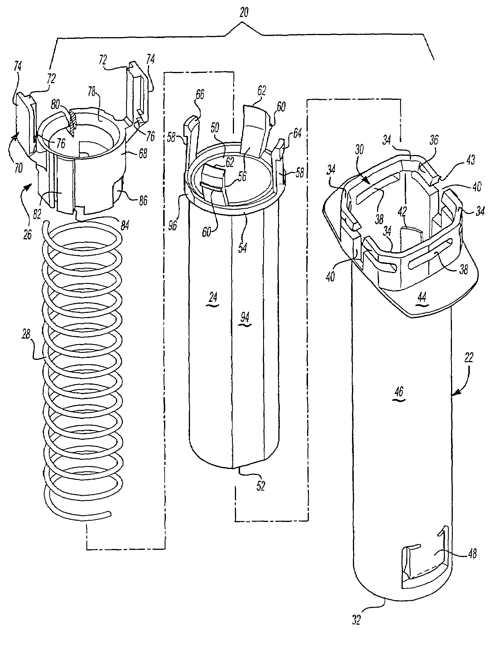
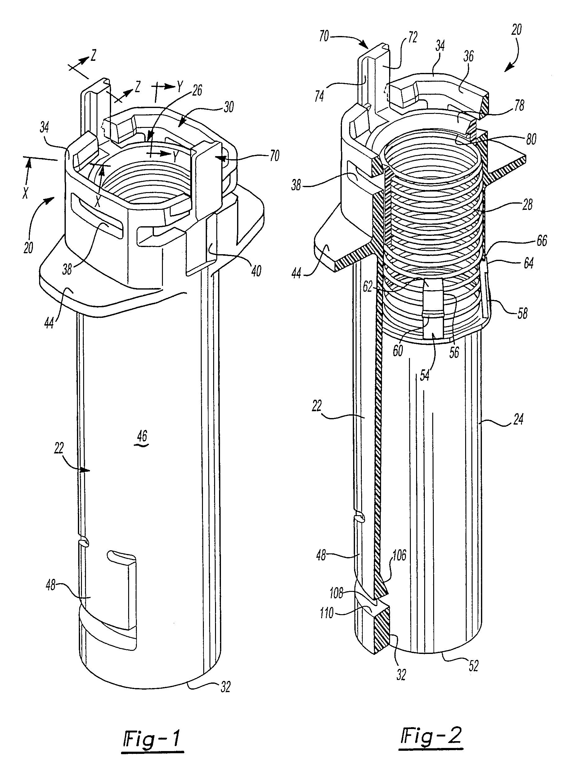
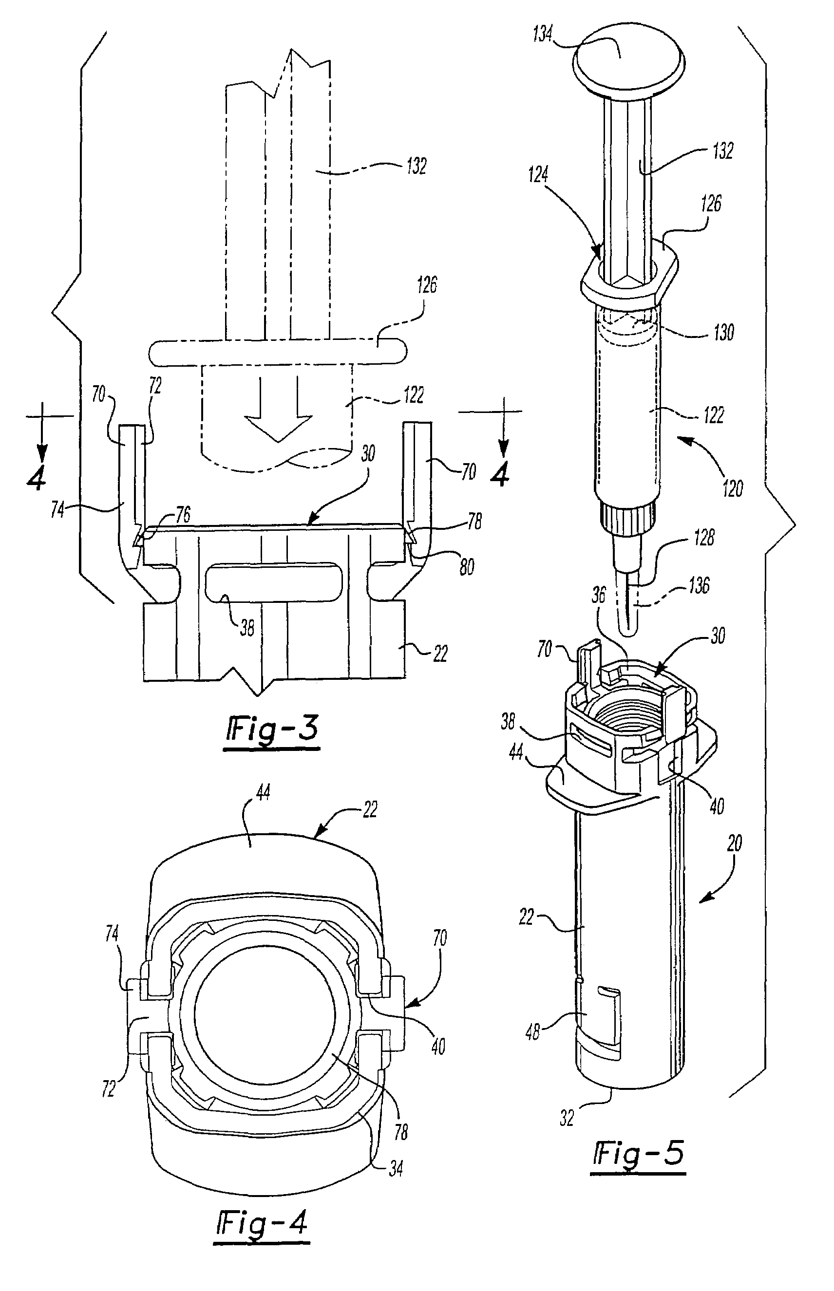
[0045]As set forth above, the preferred embodiments of the shield system 20 shown in FIGS. 1 and 2 includes four components comprising a generally tubular body 22, a generally tubular needle cover or shield 24, an annular or ring shaped member 26 and a spring 28 best shown in the exploded view of FIG. 12. The body 22 includes an open proximal end 30 and an open distal end 32. The open proximal end 30 in the disclosed embodiment is generally rectangular or square having truncated corners 34, inclined internal surfaces 36 at the open proximal end of the body, radial grooves 38 which receive the flange of the syringe described below, axial grooves 40 which extend through the proximal end on opposed sides which receive the legs of the ring shaped member 26 described below, and four radial surfaces or ledges 42 at the truncated corners 34 shown in FIG. 12 which receive the radial portions of the fingers of the needle guard or shield 24 as also described below. The open proximal end 30 of...


PUM

PropertyMeasurementUnit
mechanical interlockaaaaaaaaaa
movementaaaaaaaaaa
forceaaaaaaaaaa

Abstract

A passive shield system for a syringe including a body, shield, spring and ring which provide an interlock of the shield in the retracted position prior to receipt of the syringe for bulk transportation and processing and wherein the user selects the timing of the release of the shield to its extended position following injection, but which assures shielding of the syringe needle following release of the syringe plunger.

Description

[0001]This is a divisional of U.S. application Ser. No. 10 / 143,414, filed May 10, 2002 now U.S. Pat. No. 6,776,777.FIELD OF THE INVENTION[0002]The present invention relates to a passive shield system for injection devices, including syringes, which prevents inadvertent or premature actuation of the shield during normal bulk transportation, handling and processing and permits the user, such as a healthcare worker or patient, to select the timing of the actuation of the shield while assuring shielding of the needle or cannula without additional manual manipulation.BACKGROUND OF THE INVENTION[0003]Injection devices including syringes are well known medical devices for administering medicaments, drugs and vaccines to patients. As used herein, the term “syringe” is intended to cover the various types of injection and medical delivery devices. They are also used for other well known purposes in the medical field. Prefilled syringes, for example, are generally considered as those which are...

Claims


Application Information

Patent Timeline
Patent Type & Authority Patents(United States)
IPC IPC(8): A61M31/00A61M5/32
CPCA61M5/326A61M2005/3261Y10T29/49826Y10T29/49828A61M2005/3264A61M2207/00
Inventor BARRELLE, LAURENT
Owner BECTON DICKINSON & CO
Why Eureka
Try Eureka