Textured and drug eluting coronary artery stent

Inactive Publication Date: 2006-05-09
LEDERGERBER WALTER J
View PDF21 Cites 65 Cited by
  • Summary
  • Abstract
  • Description
  • Claims
  • Application Information

AI Technical Summary

Benefits of technology

[0017]After the stent-graft is introduced into the body lumen, the stent-graft is advanced to a desired location within the body lumen. Introducing the stent-graft i

Problems solved by technology

Furthermore, the expansion of the expandable wireframe of the stent may damage the body by morcellating plaque, thereby increasing the risk of plaque causing an embolism in a segment of

Method used


Image

  • Textured and drug eluting coronary artery stent
  • Textured and drug eluting coronary artery stent
  • Textured and drug eluting coronary artery stent

Examples


Embodiment Construction

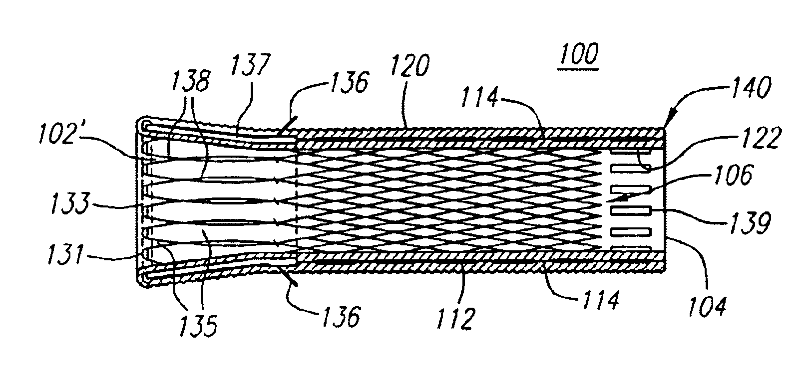
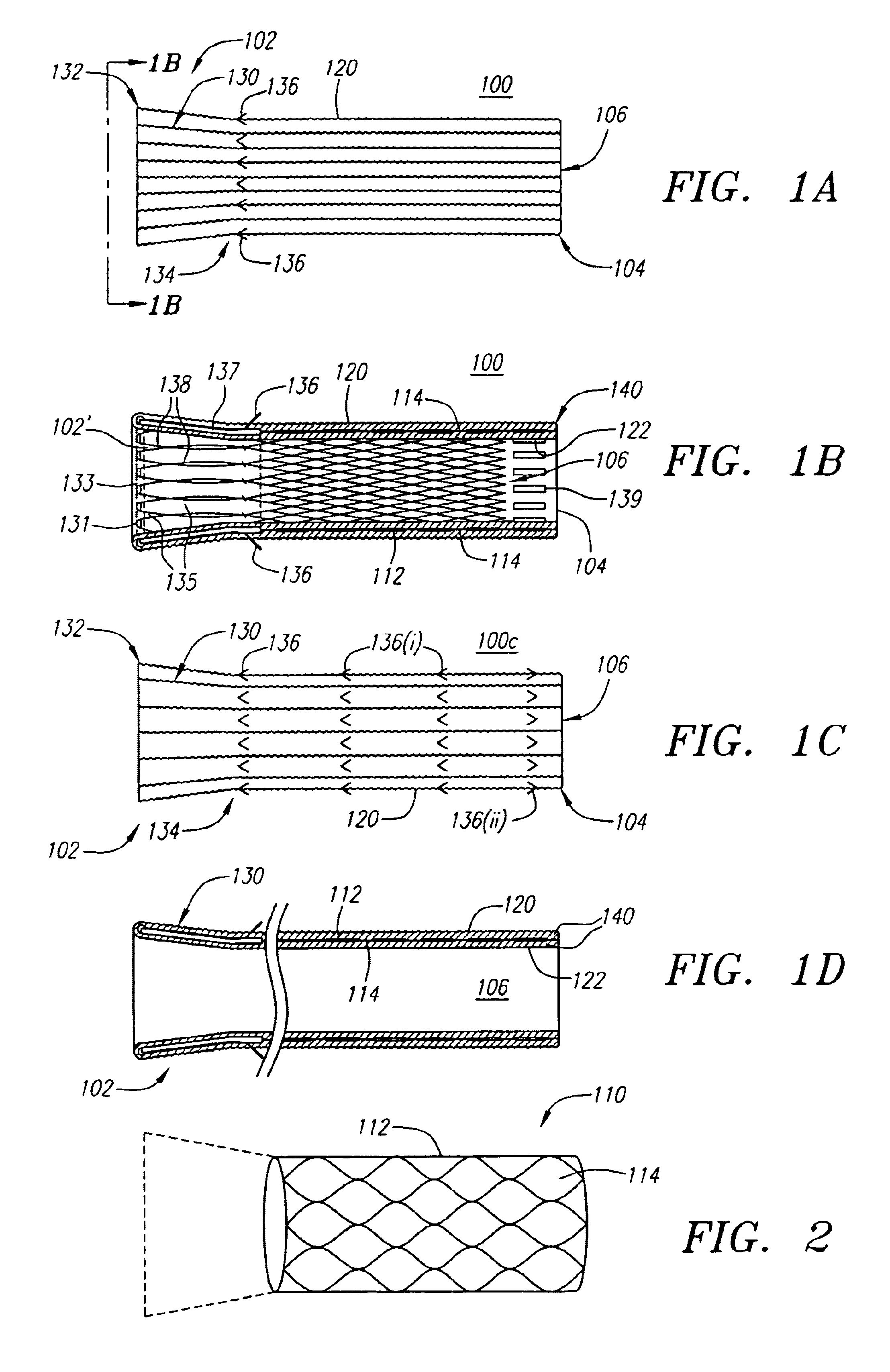
[0048]Turning now to the drawings, FIGS. 1A and 1B illustrate one embodiment of the stent-graft 100 of the present invention. FIG. 1A shows a side view of the stent-graft 100, and FIG. 1B shows a cross-sectional side view of the stent-graft 100 along the line 1B—1B in FIG. 1A. The stent-graft 100 includes a stent 110, which is best illustrated in FIG. 1B, a textured external surface layer 120, a smooth internal luminal surface layer 122, which is best seen in FIG. 1B, and a collar 130. The stent-graft 100 is a generally tubular device, having a proximal end 102, a distal end 104, and a lumen 106 therebetween. As referenced herein, the proximal end 102 of the stent-graft 100 is the end of the stent-graft 100 that confronts or is oriented towards the flow of fluid in a body lumen, and is the end of the stent-graft 100 that is generally nearest the user or physician while the user is positioning the stent-graft 100 in the body lumen. For example, when placed within a coronary artery, t...


PUM


Abstract

The present invention provides for reinforced and drug eluting stent-grafts and related methods of implanting and manufacturing the stent-grafts. A stent-graft of the present invention may include a tubular stent, a biocompatible covering surrounding the stent, and a supporting collar coupled to the proximal end of the stent-graft. A drug agent may be applied to a textured external surface layer of the biocompatible covering, or alternatively to a space between the textured external surface layer and a smooth luminal surface layer of the biocompatible covering, and allowed to elute over time into a wall of a body lumen after the stent-graft is deployed. The collar of the stent-graft absorbs pressure exerted on the stent-graft by fluid flow within the body lumen in order to minimize potential damage to the stent-graft, and may also include barbs to further secure the stent-graft to the body lumen.

Description

RELATED APPLICATION INFORMATION[0001]This application is a continuation-in-part of application Ser. No. 10 / 447,453, filed May 28, 2003, entitled “Textured and Drug Eluting Strent-Grafts”, which is incorporated herein by reference as if fully set forth herein.FIELD OF THE INVENTION[0002]The present invention relates generally to implantable prostheses for body lumens, and more particularly to drug eluting and textured stent-grafts and stent-grafts specially configured for disposition within body lumens.BACKGROUND[0003]A typical stent used in clinical practice has an expandable metal wireframe and, accordingly, contains large voids that do not necessarily contribute to either the containment or the compression of plaque. Furthermore, the expansion of the expandable wireframe of the stent may damage the body by morcellating plaque, thereby increasing the risk of plaque causing an embolism in a segment of the body lumen downstream from the stent. For example, even with the development o...

Claims


Application Information

Patent Timeline
IPC IPC(8): A61F2/06A61F2/00
CPCA61F2/07A61F2002/072A61F2/90Y10S623/901A61F2/89A61F2250/0068A61F2240/004
Inventor LEDERGERBER, WALTER J.
Owner LEDERGERBER WALTER J
Why Eureka
Try Eureka