Methods for forming and fabricating textured and drug eluting coronary artery stent

a textured, textured technology, applied in the direction of prosthesis, colloidal chemistry, blood vessels, etc., can solve the problems of increasing the risk of plaque causing an embolism, limited amount of drug agent that may be applied to the stent, and rapid elution rate of drug into the body lumen, etc., to achieve the effect of improving performan

Inactive Publication Date: 2007-09-25
LEDERGERBER WALTER J
View PDF1 Cites 57 Cited by
  • Summary
  • Abstract
  • Description
  • Claims
  • Application Information

AI Technical Summary

Benefits of technology

[0009]The biocompatible covering is preferably formed from a biocompatible material. The biocompatible materials suitable for use with the present invention are materials such as expanded polytetrafluoroethylene (ePTFE) that promote tissue in-growth into the material, and are biologically inert, non-biodegradable when implanted in the body, non-thrombogenic, lightweight, and pliable.
[0012]The collar of the stent-graft is coupled to the proximal end of the stent layer by layer and includes a wire structure surrounded by a biocompatible material, an atraumatic proximal end, and a distal end coupled to the proximal end of the stent. The wire structure may be spiral-wound radially in a tubular plane paraxial to the central axis of the stent. The collar may further incorporate a plurality of barbs arrayed circumferentially around the distal end of the collar. The barbs are configured to anchor the stent-graft to a wall of the body within which the stent-graft is deployed. The leading overmolded wire loop edge enhances the atraumatic character of the proximal end of the collar, and also enhances the ability of the collar to absorb and distribute any pressurized flow of fluids against the stent-graft. In one embodiment, the leading edge of the collar, being silicone elastomer molded over wire loops, is marginally larger in diameter than the diameter of the wire structure of the collar.
[0014]The collar of the stent-graft includes a wire structure that is surrounded by a biocompatible material, an atraumatic proximal end, and a distal end. The distal end of the collar is coupled to or is disposed near the proximal end of the stent. The collar is configured to expand and contract in unison or in conformity with the expandable frame of the stent. In one embodiment, the wire structure of the collar includes a plurality of loops, and each loop has a proximal end and a distal end. The proximal end of each loop may be oriented perpendicular to a central axis of the lumen of the stent in order to increase the atraumatic character of the proximal end of the collar. Preferably, the distal end of each loop includes a plurality of barbs, and more preferably includes two barbs. The barbs extend radially away from the stent-graft and are configured to engage a wall of a body lumen after the stent-graft is deployed within the body lumen. The collar may also incorporate a leading edge of biocompatible material on the proximal end that extends proximally from the wire structure, and which may be marginally greater in diameter than the wire structure.
[0017]After the stent-graft is introduced into the body lumen, the stent-graft is advanced to a desired location within the body lumen. Introducing the stent-graft into the body lumen and advancing the stent-graft within the body lumen may be accomplished while using a guidewire to assist maneuvering and placing the stent-graft.
[0024]The texture of the ePTFE tubular material of the stent has enhanced performance as the result of its microstructural topography created by cutting directly into the material. The ePTFE crystalline structure is cut and avulsed simultaneously by using high speed milling technique.

Problems solved by technology

Furthermore, the expansion of the expandable wireframe of the stent may damage the body by morcellating plaque, thereby increasing the risk of plaque causing an embolism in a segment of the body lumen downstream from the stent.
Currently, the amount of a drug agent that may be applied to a stent is limited and the rate of elution of the drug into the body lumen is rapid.

Method used


Image

  • Methods for forming and fabricating textured and drug eluting coronary artery stent
  • Methods for forming and fabricating textured and drug eluting coronary artery stent
  • Methods for forming and fabricating textured and drug eluting coronary artery stent

Examples


Embodiment Construction

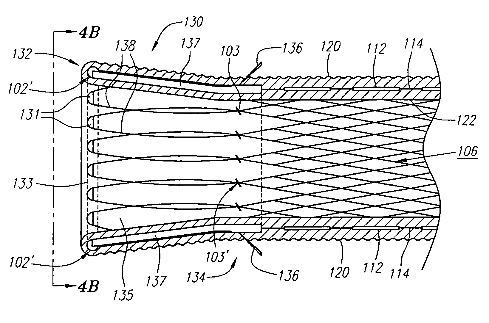
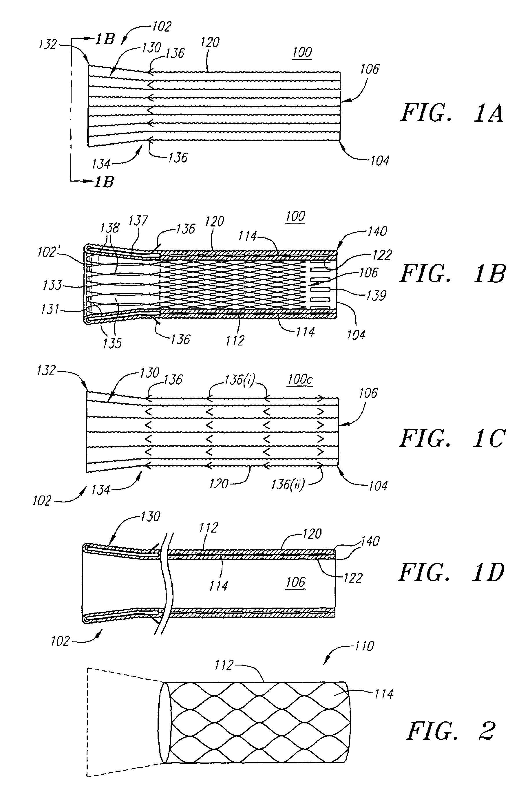
[0053]Turning now to the drawings, FIGS. 1A and 1B illustrate one embodiment of the stent-graft 100 of the present invention. FIG. 1A shows a side view of the stent-graft 100, and FIG. 1B shows a cross-sectional side view of the stent-graft 100 along the line 1B-1B in FIG. 1A. The stent-graft 100 includes a stent 110, which is best illustrated in FIG. 1B, a textured external surface layer 120, a smooth internal luminal surface layer 122, which is best seen in FIG. 1B, and a collar 130. The stent-graft 100 is a generally tubular device, having a proximal end 102, a distal end 104, and a lumen 106 therebetween. As referenced herein, the proximal end 102 of the stent-graft 100 is the end of the stent-graft 100 that confronts or is oriented towards the flow of fluid in a body lumen, and is the end of the stent-graft 100 that is generally nearest the user or physician while the user is positioning the stent-graft 100 in the body lumen. For example, when placed within a coronary artery, t...


PUM


Abstract

The present invention provides for reinforced and drug eluting stent-grafts and related methods of implanting and manufacturing the stent-grafts. A stent-graft of the present invention may include a tubular stent, a biocompatible covering surrounding the stent, and a supporting collar coupled to the proximal end of the stent-graft. A drug agent may be applied to a textured external surface layer of the biocompatible covering, or alternatively to a space between the textured external surface layer and a smooth luminal surface layer of the biocompatible covering, and allowed to elute over time into a wall of a body lumen after the stent-graft is deployed. The collar of the stent-graft absorbs pressure exerted on the stent-graft by fluid flow within the body lumen in order to minimize potential damage to the stent-graft, and may also include barbs to further secure the stent-graft to the body lumen.

Description

RELATED APPLICATION INFORMATION[0001]This application is continuation-in-part of application Ser. No. 10 / 698,712, filed Oct. 31, 2003, entitled “Textured and Drug Eluting Coronary Artery Stent”, which issued as U.S. Pat. No. 7,041,127 on May 9, 2006, which is a continuation-in-part of application Ser. No. 10 / 447,453, filed May 28, 2003, entitled “Textured and Drug Eluting Strent-Grafts”, now abandoned, which are incorporated herein by reference as if fully set forth herein.FIELD OF THE INVENTION[0002]The present invention relates generally to implantable prostheses for body lumens, and more particularly to drug eluting and textured stent-grafts and stent-grafts specially configured for disposition within body lumens.BACKGROUND[0003]A typical stent used in clinical practice has an expandable metal wireframe and, accordingly, contains large voids that do not necessarily contribute to either the containment or the compression of plaque. Furthermore, the expansion of the expandable wire...

Claims


Application Information

Patent Timeline
Patent Type & Authority Patents(United States)
IPC IPC(8): A61F2/06A61F2/00
CPCA61F2/07A61F2002/072A61F2/90Y10S623/901A61F2/89A61F2250/0068A61F2240/004
Inventor LEDERGERBER, WALTER J.
Owner LEDERGERBER WALTER J
Why Eureka
Try Eureka