Process for manufacturing a micro-fluid ejection device

a technology of microfluid ejection and manufacturing process, which is applied in the field of microfluid ejection devices, can solve the problems of limited fluid passageway spacing in the ejection head substrate, difficulty in adequately segregating multiple fluids in the cartridge from one another, and reducing the efficiency of ejection head production, so as to reduce the cost of manufacturing, reduce the size of the operative part, and improve the effect of ejection speed

Active Publication Date: 2006-05-16
FUNAI ELECTRIC CO LTD
View PDF22 Cites 5 Cited by
  • Summary
  • Abstract
  • Description
  • Claims
  • Application Information

AI Technical Summary

Benefits of technology

[0006]One advantage of the apparatus and methods disclosed herein could be that multiple different fluids can be ejected from a micro-fluid ejection device that is less costly to manufacture and has dimensions that enable increased miniaturization of operative parts of the device. Continued miniaturization of the operative parts enables micro-fluid ejection devices to be used in a wider variety of applications. Such miniaturization also enables the production of ejection devices, such as printers, having smaller footprints without sacrificing print quality or print speed. The apparatus and methods described might reduce the size of a silicon substrate used in such micro-fluid ejection devices without sacrificing the ability to suitably eject multiple different fluids from the ejection device.

Problems solved by technology

However, the trend is to further miniaturize the ejection devices and thus provide smaller ejection head substrates.
However, this trend leads to challenges relating to attaching such substrates to a multi-fluid supply reservoir.
As the ejection heads are reduced in size, it becomes increasingly difficult to adequately segregate multiple fluids in the cartridges from one another yet provide the fluids to different areas of the ejection heads.
One of the limits on spacing of fluid passageways in the ejection head substrate is an ability to provide correspondingly small, and closely-spaced passageways from the fluid reservoir to the ejection head substrate.
Another limit on fluid passageway spacing is the ability to adequately align the passageways in the fluid reservoir with the passageways in the ejection head substrate so that the passageways are not partially or fully blocked by an adhesive used to attach to the ejection head to the reservoir.

Method used


Image

  • Process for manufacturing a micro-fluid ejection device
  • Process for manufacturing a micro-fluid ejection device
  • Process for manufacturing a micro-fluid ejection device

Examples


Embodiment Construction

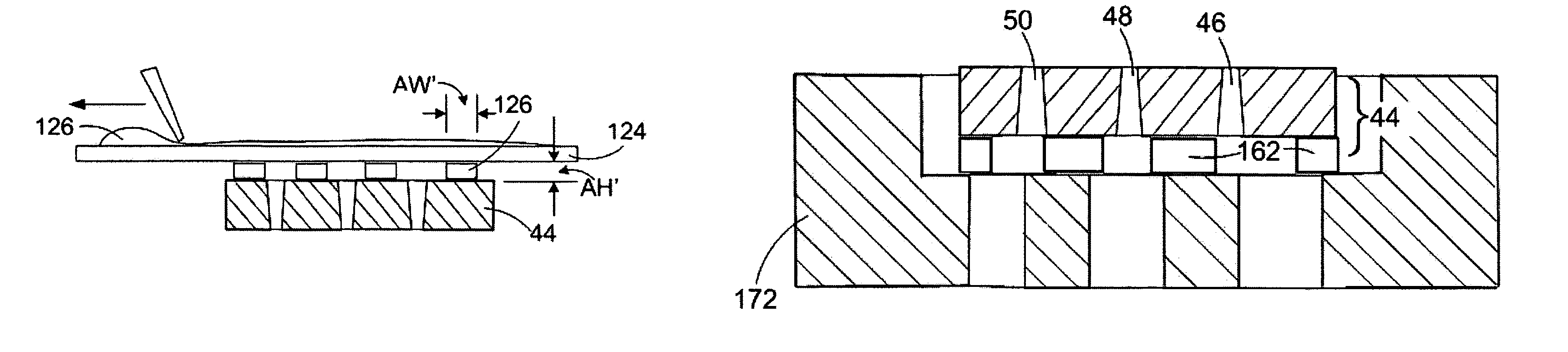
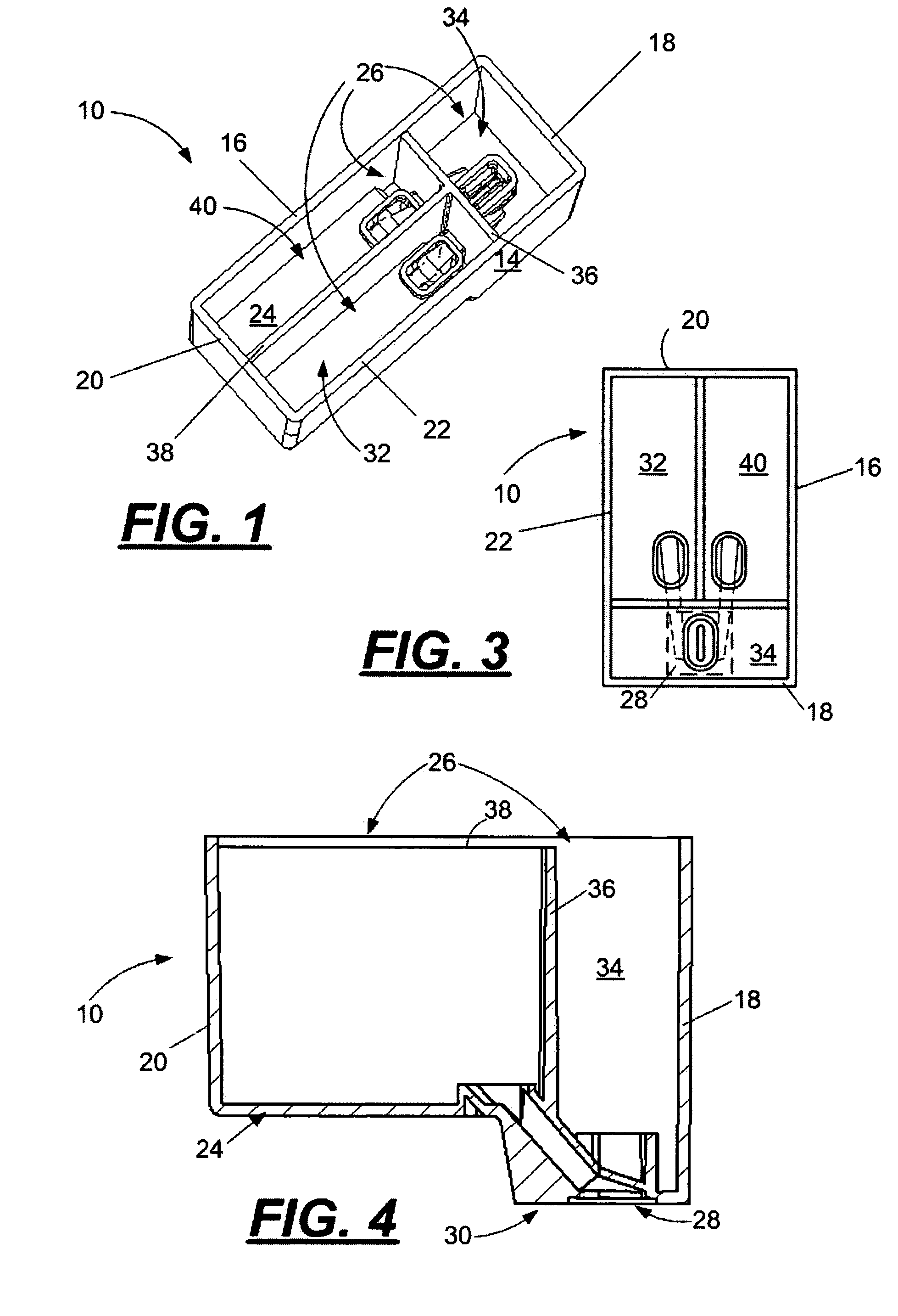
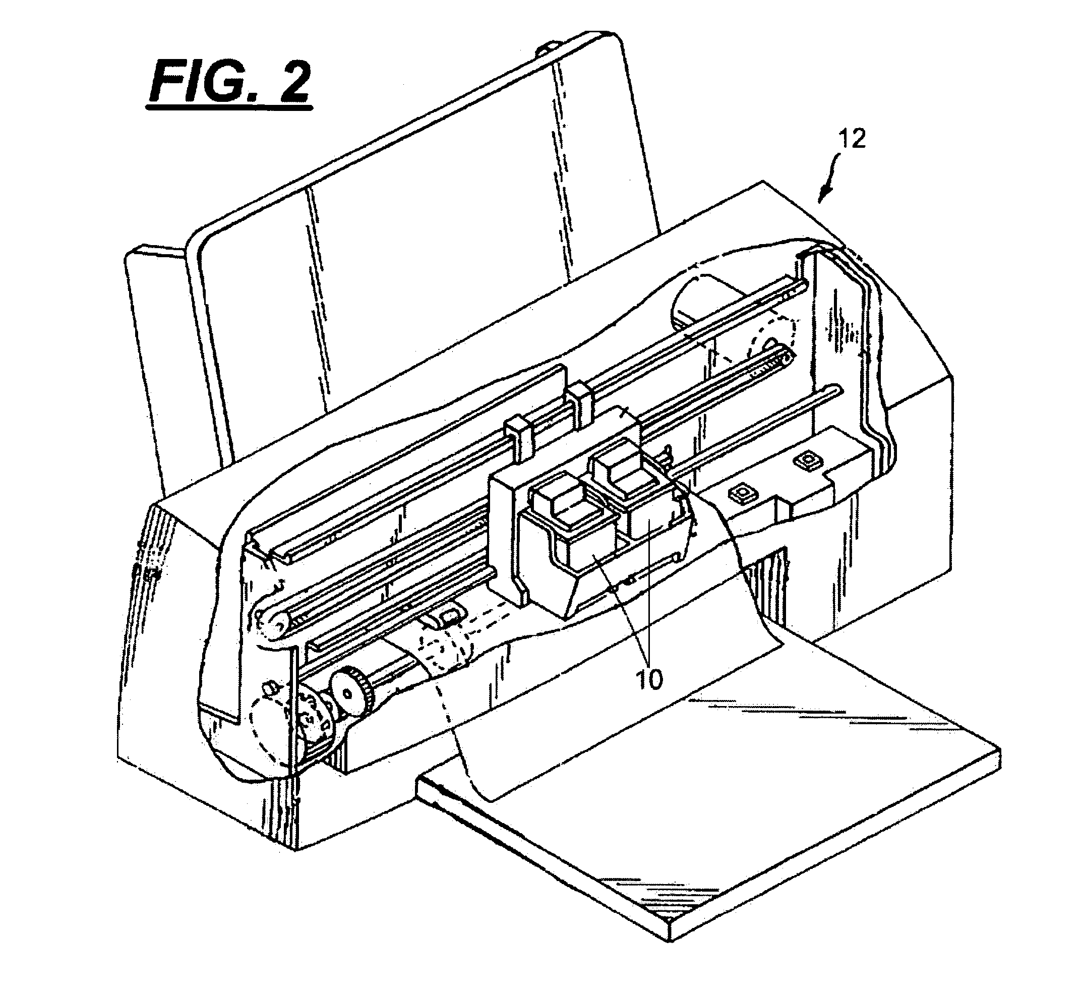
[0028]With reference to FIGS. 1–5, a multi-fluid cartridge body 10 for a micro-fluid ejection device, such as an ink jet printer 12 is illustrated. The multi-fluid body 10 includes a body structure 14 having exterior side walls 16, 18, 20, and 22 and a bottom wall 24 forming an open-topped, interior cavity 26. An ejection head area 28 is disposed adjacent a portion 30 of the bottom wall 24 opposite the interior cavity 26. At least two segregated fluid chambers 32 and 34 are provided within the interior cavity 26 of the body 10. A dividing wall 36 separates chamber 32 from chamber 34. An additional dividing wall 38 may be provided to separate chamber 40 from chamber 32 for a body 10 containing three different fluids. Independent fluid supply paths are provided from each of the fluid chambers 32, 34, and 40 to provide fluid to an ejection head structure 44 attached adjacent the ejection head area 28 of the body 10. The fluids are retained in the chambers 32, 34, and 40 by a cover 42 a...


PUM

PropertyMeasurementUnit
widthaaaaaaaaaa
heightaaaaaaaaaa
height AHaaaaaaaaaa

Abstract

A method is provided for making a multi-fluid cartridge for holding multiple fluids in segregated containment localities. The cartridge body contains fluid supply paths in fluid flow communication with the containment localities. A nozzle plate is attached to a device side of each of a plurality of defined ejection head substrates on a semiconductor wafer. Each of the ejection head substrates has a fluid supply side and two or more fluid flow paths therein for supplying fluid from the supply side to the device side thereof. The fluid flow paths in the ejection head substrates have a flow path density of greater than about 1.0 flow paths per millimeter. The wafer is diced to provide a plurality of micro-fluid ejection device structures. A circuit device is attached to the device side of each of the substrates. An adhesive is stencil printed with a bond line density of at least about 1.2 mm−1 on the micro-fluid ejection device structures or on the cartridge body. At least one of the micro-fluid ejection device structures and attached circuit is adhesively bonded to the cartridge body for flow of fluid from the containment localities to the device side thereof.

Description

FIELD OF THE INVENTION[0001]The disclosure relates to micro-fluid ejection devices and in particular to structures and techniques for securing a semiconductor substrate to a multi-fluid reservoir.BACKGROUND OF THE INVENTION[0002]In the field of micro-fluid ejection devices, ink jet printers are an exemplary application where miniaturization continues to be pursued. However, as micro-fluid ejection devices get smaller, there is an increasing need for unique designs and improved production techniques to achieve the miniaturization goals. For example, the increasing demand of putting more colors in a single inkjet cartridge requires the addition of fluid flow passageways from the cartridge body to the ejection head that, without radical changes in production techniques, will require larger ejection head substrates. However, the trend is to further miniaturize the ejection devices and thus provide smaller ejection head substrates. An advantage of smaller ejection head substrates is a re...

Claims


Application Information

Patent Timeline
Patent Type & Authority Patents(United States)
IPC IPC(8): B21D53/76B32B38/14H05K3/32
CPCB41J2/17513B41J2/1752B41J2/17526B41J2/17553B41J2/17559C07D235/18C07D403/12C07D401/12Y10T29/4913Y10S29/001Y10T29/49401Y10T156/1062Y10T29/49798Y10T29/49155B21D53/76H05K3/32
Inventor SMOOT, MARY C.SPIVEY, PAUL T.WALDECK, MELISSA M.BERTELSEN, CRAIG M.WEAVER, SEAN T.
Owner FUNAI ELECTRIC CO LTD
Why Eureka
Try Eureka