Pivoting jaw pipe wrench

a technology of pivoting jaw and wrench, which is applied in the field of pipe wrenches, can solve the problems of inefficient gripping performance, undesirable slippage between the wrench and the pipe, slippage and potential damage to the workpiece as well as the teeth on the jaws of the wrench, etc., and achieves improved gripping performance, improved gripping performance, and improved gripping performance.

Inactive Publication Date: 2006-05-16
EMERSON ELECTRIC CO
View PDF13 Cites 24 Cited by
  • Summary
  • Abstract
  • Description
  • Claims
  • Application Information

AI Technical Summary

Benefits of technology

[0005]In accordance with the present invention, a pivoting jaw pipe wrench is provided by which improved gripping performance is achieved with respect to a large range of pipe sizes which could not be satisfactorily accommodated in a single pivoting jaw wrench heretofore available. More particularly in this respect, improved gripping performance is achieved by providing a discrete tooth on the fixed jaw for each different size pipe to be gripped by the wrench while maintaining a functional pivot angle of 90° for the pivotal jaw. With regard to the latter, the working angle for the wrench is 90° and the actual angle is about 98° to provide an allowance for over travel. Further, an optimum camming angle is maintained for a given discrete tooth and pipe size combination and, preferably, each discrete tooth has a preferred included angle and preferred rake and relief angles relative to a diametrical line through the pipe and the apex of the tooth. The provision of a discrete tooth for each different pipe diameter together with a preferred camming angle for the tooth results in improved gripping performance relative to similar wrenches heretofore available, and the provision of a specific orientation of the tooth relative to the center of the corresponding pipe to be gripped and specific rake and relief angles for the tooth further improves the gripping performance.
[0006]In connection with a series of pipes having nominal diameters between ⅜ inch and 2 inches, and a pivotal jaw having a working pivot angle of displacement of 90° between the closed and open positions thereof, an improved gripping performance is achieved with a camming angle maintained between 90° and 150° for each of the discrete teeth provided on the arcuate jaw face for the different diameter pipes. Further, optimum gripping performance is realized when the discrete teeth for camming angles between 131° and 150° have an included angle of 90°, a relief angle of 40° and a rake angle of −40°. Likewise, optimum gripping performance is achieved when the discrete teeth providing camming angles between 90° and 130° have an included angle of 55°, a relief angle of 25°, and a rake angle of 10°. An acceptable range for each of the included, relief and rake angles is ±5°.
[0007]It is accordingly an outstanding object of the present invention to provide a pivoting jaw pipe wrench which accommodates a large range of pipe sizes and provides improved gripping performance with respect thereto relative to pivoting jaw pipe wrenches heretofore available.

Problems solved by technology

However, the gripping capability of such wrenches is compromised when a large range of pipe sizes are required to be gripped while limiting the rotational swing of the pivotal jaw to 90° to facilitate operability of the wrench.
In this respect, a large range of pipe sizes and the limitation of a 90° swing of the pivotal jaw results in undesirable slippage between the wrench and pipe in connection with the turning of larger sizes of pipe such as 1½ inches to 2 inches and larger diameter pipe.
Further in this respect, a line from the pivot axis of the pivotal jaw to a given point on the arcuate jaw face and from the latter point through the vertex between the sets of teeth on the pivotal jaw provides a camming angle for a given diameter pipe and, in many pivoting jaw wrenches heretofore provided, the camming angle becomes unfavorable on the larger sizes of pipes which results in inefficient gripping performance, slippage and potential damage to the workpiece as well as the teeth on the jaws of the wrench.

Method used


Image

  • Pivoting jaw pipe wrench
  • Pivoting jaw pipe wrench
  • Pivoting jaw pipe wrench

Examples


Embodiment Construction

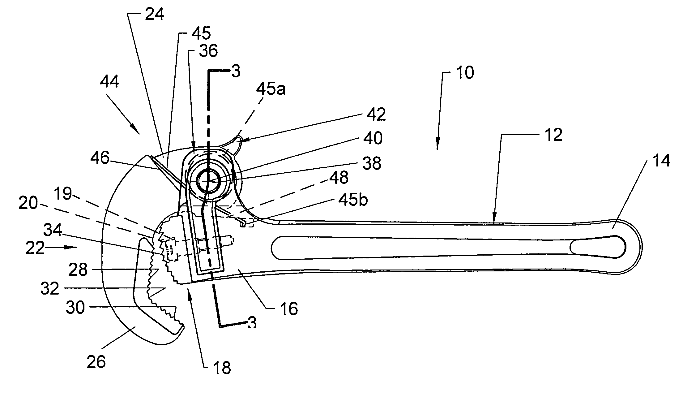
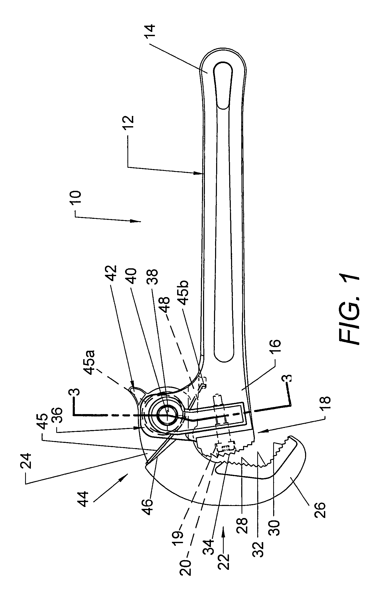
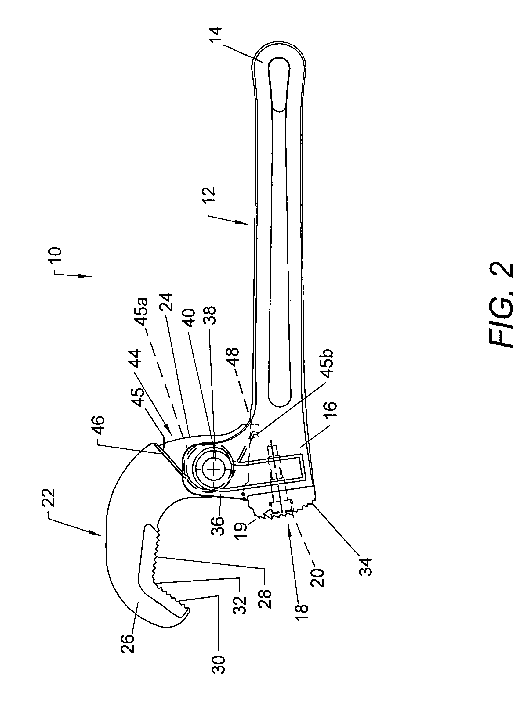
[0022]Referring now in greater detail to the drawings, wherein the showings are for the purpose of illustrating preferred embodiments of the invention only and not for limiting the invention, FIGS. 1–4 illustrate a pivoting jaw pipe wrench 10 in accordance with the invention and which includes a handle 12 having longitudinally opposite ends 14 and 16 and an arcuate fixed jaw at end 16 which, in the illustrated embodiment, is provided by heel jaw member 18 which is described in greater detail hereinafter and which includes a stepped bore 19 therethrough by which it is mounted on handle 12 by a threaded fastener 20. Wrench 10 further includes a pivotal jaw member 22 having a mounting end 24 and a jaw end 26 provided with first and second linear jaw faces having teeth 28 and 30, respectively. The jaw faces are at an angle to one another which can be from 90° to 130° and which is nominally 120° and, preferably, 119° to accommodate gripping hex pipe unions. Teeth 28 and 30 are of standar...


PUM


Abstract

A pivoting jaw pipe wrench comprises a fixed jaw including a plurality of discrete teeth, each for a different one of a plurality of pipes having different diameters. A pivotal jaw member has first and second jaw faces at an obtuse angle to one another and displaceable toward and away from the fixed jaw, whereby a pipe of given diameter to be gripped by the wrench is cradled between the first and second jaw surfaces and engaged by the one of the discrete teeth provided on the arcuate jaw for the pipe of given diameter.

Description

[0001]This patent application is a continuation of application Ser. No. 10 / 144,122 filed on May 10, 2002, and incorporated herein by reference and which application issued Jun. 1, 2004 as U.S. Pat. No. 6,742,419.BACKGROUND OF THE INVENTION[0002]This invention relates to the art of pipe wrenches and more particularly, to improvements in pivoting jaw pipe wrenches.[0003]Pivoting jaw pipe wrenches are known as shown, for example, in U.S. Pat. No. 2,028,406 to Mead and U.S. Pat. No. 2,559,973 to Kunz. Such wrenches typically include a handle having a fixed toothed jaw at one end thereof and a toothed jaw member pivotally mounted on the one end for displacement toward and away from the fixed jaw. The pivotal jaw member has teeth thereon which are cooperable with the teeth on the fixed jaw to grip a pipe or other workpiece therebetween, and the pivotal jaw is spring biased toward the fixed jaw to provide a closing force against the pipe or workpiece therebetween. In the Mead patent, the t...

Claims


Application Information

Patent Timeline
Patent Type & Authority Patents(United States)
IPC IPC(8): B25B13/28B25B13/50
CPCB25B13/505B25B13/28
Inventor CHARTIER, GLEN R.MACHOVINA, DAVID L.MANDELL, CHRIS W.
Owner EMERSON ELECTRIC CO
Why Eureka
Try Eureka