Heat exchanger and related exchange module

Inactive Publication Date: 2006-05-16
ZIEPACK
View PDF19 Cites 42 Cited by
  • Summary
  • Abstract
  • Description
  • Claims
  • Application Information

AI Technical Summary

Benefits of technology

[0018]In general, one of the very significant innovative aspects of the present invention, which can equally well be found in the preferred embodiment of the U-shape bend and in the preferred embodiment of the end zone of the channels, is the production of curved weld seams, preferably circular, making it possible to produce channels by hydroforming that are themselves curved and preferably circular and having a substantially preserved cross-section.
[0019]One of the difficulties of hydroforming is that, during the inflation, certain zones constitute stiffeners preventing the correct deformation of other zones. Surprisingly, the c

Problems solved by technology

In comparison with such a saving in height, the slightly inc

Method used


Image

  • Heat exchanger and related exchange module
  • Heat exchanger and related exchange module
  • Heat exchanger and related exchange module

Examples


Example

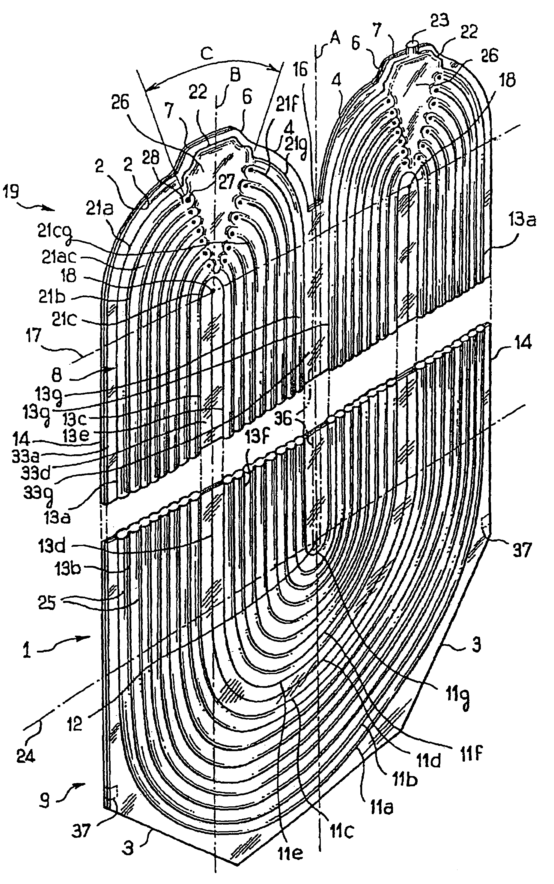
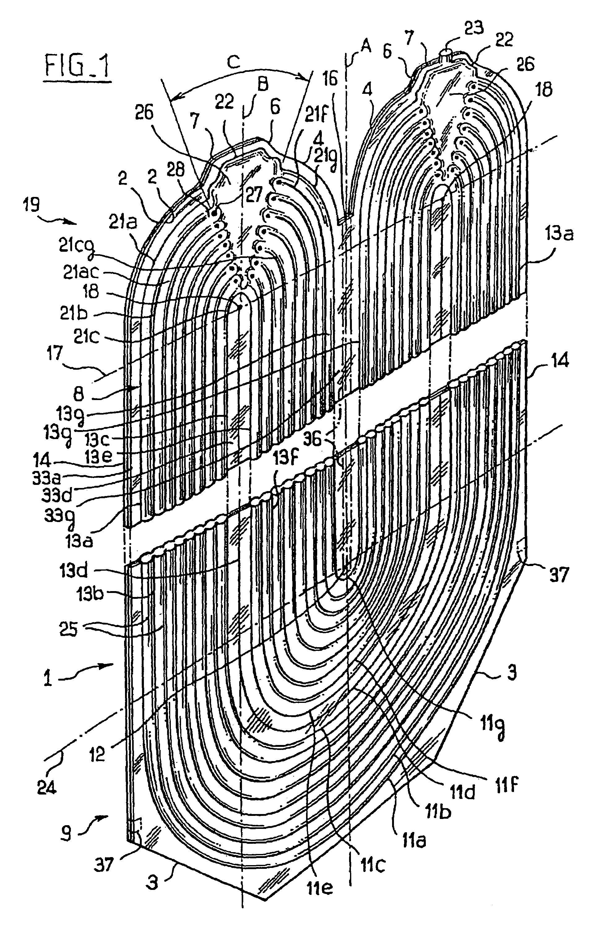
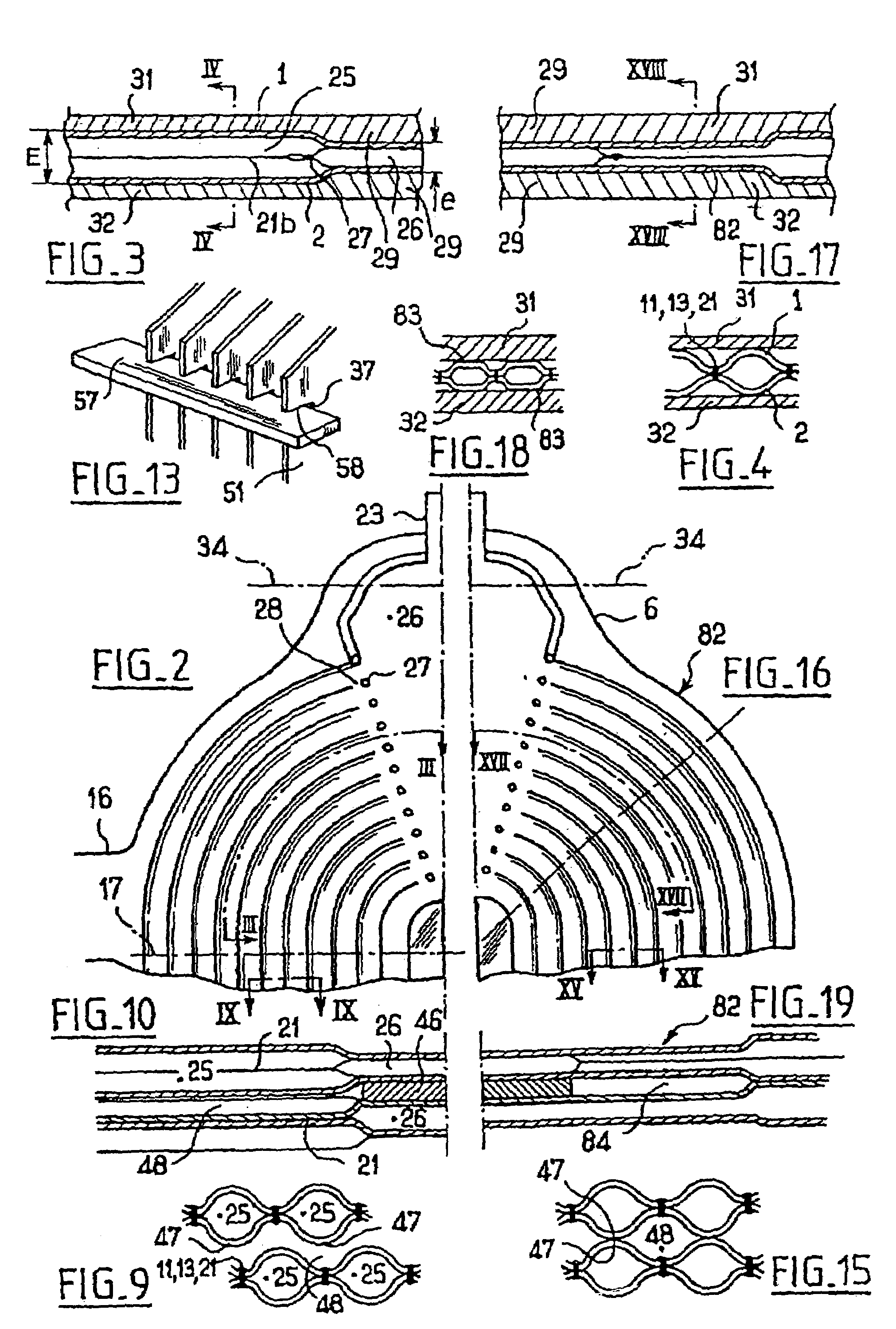
[0050]In the examples shown in FIGS. 1 to 14, a heat exchange module 1 (FIG. 1) is obtained by laser welding two initially flat metal sheets 2, cut out with an identical contour. The contour of the metal sheets 2 has a very generally rectangular shape whose length corresponds to the vertical direction of FIG. 1. At a rear end 9 of this length, each corner of the contour of the metal sheets 2 has a chamfer 3. At the other end 19 of its length, or “Module head”, the contour forms two domes 4 of generally semicircular shape disposed side by side, each extended by a protrusion 6 of generally trapezoidal shape, whose peak 7 corresponds to the small base of the trapezium.

[0051]The width of the metal sheets 2 can for example range between 100 and 1600 mm. The length of the metal sheets is limited only by the dimension of the means available for limiting the expansion in thickness during the hydroforming operation which will be described below. In practice, metal sheets of 10 meters and mor...


PUM


Abstract

A heat exchange module is disclosed comprising two metal sheets welded along weld lines defining between them a group of channels disposed side by side substantially in a common plane, intended to be passed through by an exchange fluid and, from the fluidic point of view, being in parallel with each other between two connection orifices of the module. The group of channels has a generally U-shape configuration, which connects together the said connection orifices that are laterally separated from each other.

Description

[0001]The present invention relates to a heat exchange module intended to form part of the thermally active core of a heat exchanger.[0002]The present invention also relates to a heat exchanger equipped with such a module.[0003]WO-A-98 / 16 786 describes an exchanger whose core consists of a stack of two-panel modules. Each module consists of two metal sheets defining between them a series of longitudinal and parallel channels conveying a first exchange fluid from one end to the other of the modules. The production method of such modules consists in laser welding two flat metal sheets along longitudinal and parallel lines intended to form the separations between the channels. A peripheral weld closes the space between the two metal sheets with the exception of a nozzle for the injection of water under pressure. The module is formed by injecting water under pressure between the two panels in order to produce an inflation of the two metal sheets between the weld seams.[0004]The modules ...

Claims


Application Information

Patent Timeline
IPC IPC(8): F28F3/12B21D53/04F28D9/00F28F3/14F28F9/00F28F9/02
CPCF28D9/0006F28D9/0031F28F9/005F28F9/0221F28F3/14F28F2255/10F28F2250/102
Inventor GUIDAT, ROLANDCLAUDEL, MICHELNOEL, FLORENT
Owner ZIEPACK
Why Eureka
Try Eureka