Two part candle container

a candle container and two-part technology, applied in the direction of containers, fatty acid production, heating/cooling arrangements, etc., can solve the problems of the efficiency of combustion and the problem and achieve the effect of central placement of wax and wick in the vessel and convenient placement of wax and wick

Inactive Publication Date: 2006-05-16
MLADENOVIC ROY
View PDF7 Cites 18 Cited by
  • Summary
  • Abstract
  • Description
  • Claims
  • Application Information

AI Technical Summary

Benefits of technology

[0006]Containerized candles require the correct placement of tallow or wax and a wick contained in a transparent or otherwise translucent vessel. One example of the vessel is a glass apothecary jar. The walls of the vessel prevent the loss of wax from run off when the wax is melted by the flaming wick when lit. However, one disadvantage of containerized candles is that central placement of the wax and wick in the vessel can be problematic due to a restricted neck portion at the mouth of the vessel. A further disadvantage of the containerized candles is the efficiency of their combustion, as sufficient ambient air may not be drawn to the base of the flame to oxidize carbon particles present in later stages of the combustion. A two part candle container having a cylindrical body with a closed base at one end and an open mouth at the other end of the cylindrical body can facilitate the placement of the wax and wick. The container comprises a holder f...

Problems solved by technology

However, one disadvantage of containerized candles is that central placement of the wax and wick in the vessel can be problematic due to a restricted neck portion at the mouth of the vessel.
A further disadv...

Method used


Image

  • Two part candle container
  • Two part candle container
  • Two part candle container

Examples


Embodiment Construction

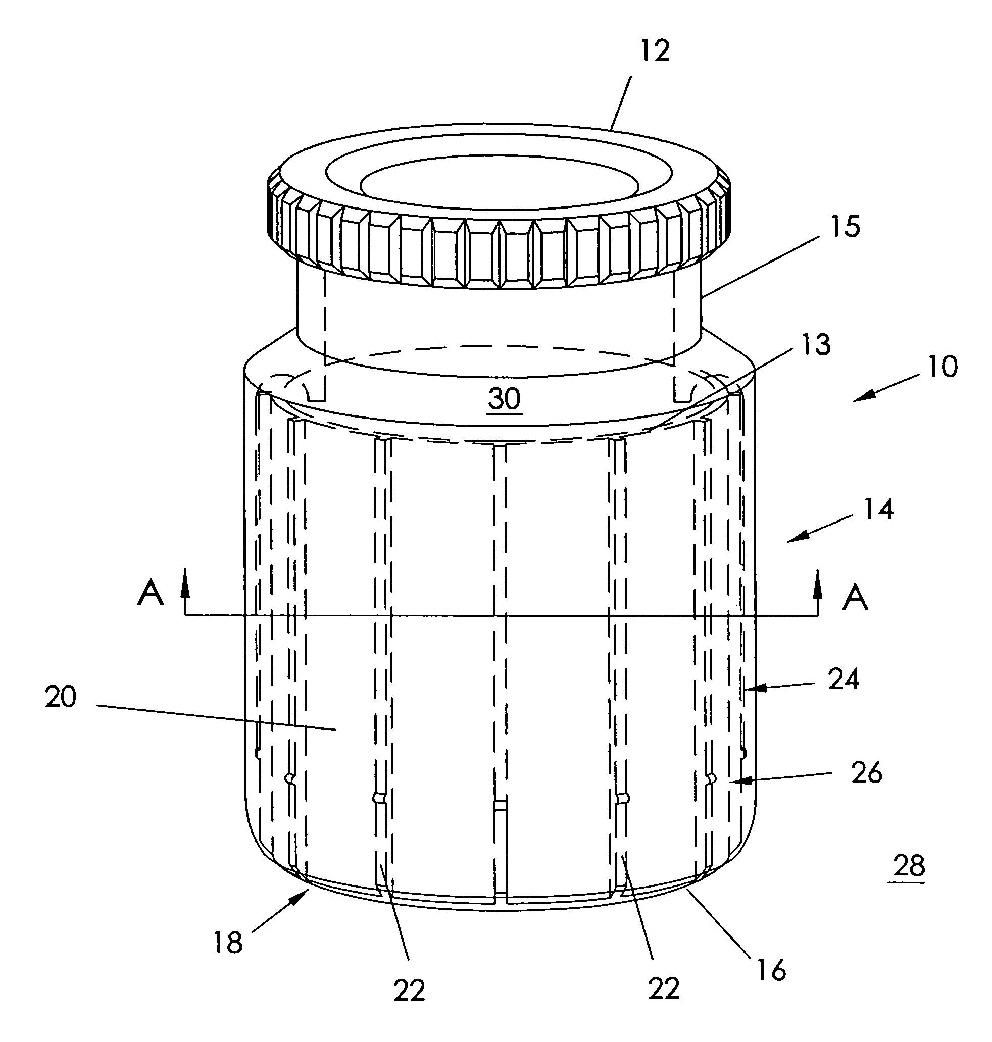
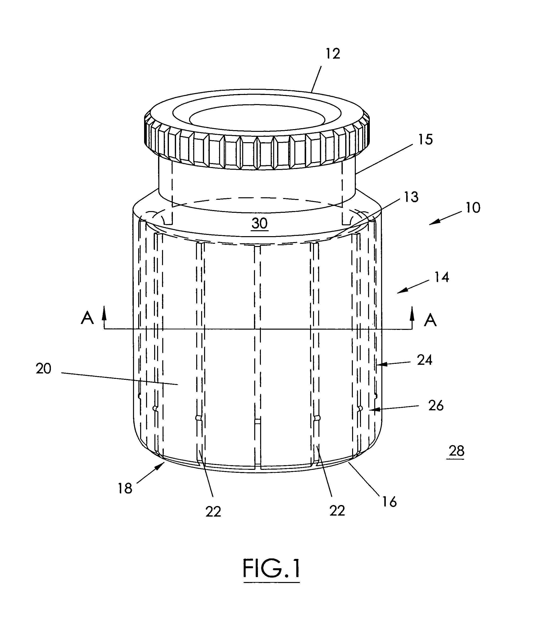
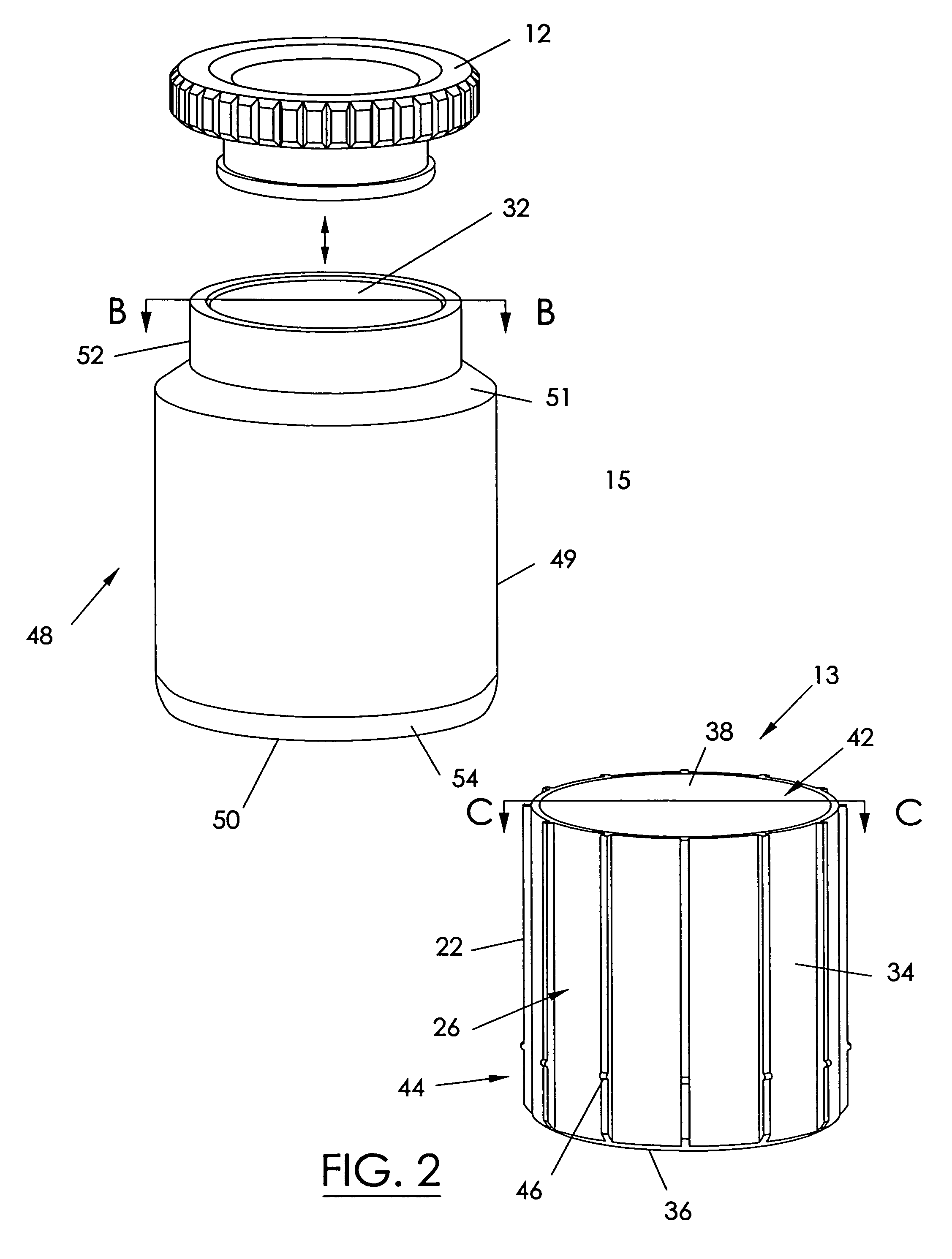
[0026]Referring to FIG. 1, a candle container 10 includes a cover 12 for covering a body 14 that is adapted to hold poured wax (not shown). The body 14 comprises two parts, namely an interior holder 13 and an exterior shell 15. A series of vents 16 extend around the periphery of a base 18 of the container 10 to supply intake air to a series of respective channels 20. Each of the channels 20 is defined as a passageway with walls consisting of a pair of adjacent splines 22, an interior surface 24 of the shell 15, and an exterior surface 26 of the bolder 13. The channels 20 extend from the vents 16 to the top of the holder 13, such that ambient air 28 is in fluid communication through the channels 20 to an interior 30 of the container 10. It should be noted that the vents 16 are placed below a mouth 32 (see FIG. 2) of the container 10.

[0027]Referring to FIG. 2, the interior holder 13 has a cylindrical sidewall 34, such as but not limited to of circular cross section, with a closed base...


PUM


Abstract

Containerized candles use the correct placement of tallow or wax and a wick contained in a transparent or otherwise translucent vessel. One example of the vessel is a glass apothecary jar. The walls of the vessel prevent the loss of wax from run off when the wax is melted by the flaming wick when lit. A two part candle container having a cylindrical body with a closed base at one end and an open mouth at the other end of the cylindrical body can facilitate the placement of the wax and wick. The container comprises a holder for providing an inner sidewall of the cylindrical body, the inner sidewall having the closed base at said one end and an open top at said other end to define a holder interior configured to receive the candle wax and wick. The holder has a full bore at the open top. The container also has a shell for providing an outer sidewall of the cylindrical body, the outer sidewall having an opening at said one end configured to receive the holder and the open mouth at said other end configured to exhaust combustion gases generated by the candle. The open mouth of the shell has a restricted portion for helping to retain the heat generated by the candle when combusted. The container also has a locking mechanism for fixedly securing the holder to the shell when assembled; wherein when assembled the shell and holder provide the cylindrical body having a pair of sidewalls consisting of the inner sidewall and the outer sidewall.

Description

BACKGROUND OF THE INVENTION[0001]Containerized candles are well known for their ability to increase the longevity of a candle. A containerized candle has tallow or wax and a wick contained in a transparent or otherwise translucent vessel, such as a glass apothecary jar. The walls of the vessel prevent the loss of wax from run off when the wax is melted by the flaming wick when lit, and can allow for a more decorative presentation when applied on the exterior surface of the vessel. However, one disadvantage of containerized candles is that central placement of the wick in the vessel can be problematic due to a restricted neck portion at the mouth of the vessel. A further disadvantage of the containerized candles is the efficiency of their combustion, as sufficient ambient air may not be drawn to the base of the flame to oxidize carbon particles present in later stages of the combustion. In some cases, incomplete combustion can cause the flame to be smoky, and the exhaust will therefo...

Claims


Application Information

Patent Timeline
IPC IPC(8): B65D21/02B65D8/12B65D8/16C11C5/00F21V35/00
CPCC11C5/008F21V35/00F21V17/007F21V29/15
Inventor MLADENOVIC, ROY
Owner MLADENOVIC ROY
Why Eureka
Try Eureka