Radial-radial single rotor turbine

a radial-radial, single-rotor technology, applied in the direction of piston pumps, marine propulsion, vessel construction, etc., can solve the problems of increased vibrational modes, increased shaft whipping, and increased cost, and the turbine entrance temperature must be more severely limited to avoid damage,

Inactive Publication Date: 2006-05-16
LOS ALAMOS NATIONAL SECURITY
View PDF52 Cites 27 Cited by
  • Summary
  • Abstract
  • Description
  • Claims
  • Application Information

AI Technical Summary

Problems solved by technology

When the rotors are on a fairly long connecting shaft, problems of balance, shaft whip, and multiple vibrational modes become exacerbated.
These problems can cause various troubles up to the failure of the machine.
In these smaller turbines, the turbine blades are not cooled, so the turbine entrance temperatures must be more severely limited to avoid damage.
However, these higher temperature materials generally are rare and quite expensive.
Likewise, these schemes are costly and inefficient.
Present turbine engines of all sizes do not operate anywhere near the theoretical maximum efficiency, and small engines, which lack feasible blade cooling schemes, are less efficient.
The mixing of the flows, sealing problems, and non standard flow passages are problems in the design of this patent, as we well as the preceding patent.
There is not yet a reliable and practical way to cool the turbine of gas turbine machinery.
Multiple rotor turbo machines such as engines, turbochargers, refrigeration compressors, and others all suffer from dynamic problems caused by the shaft and rotor system.

Method used


Image

  • Radial-radial single rotor turbine
  • Radial-radial single rotor turbine
  • Radial-radial single rotor turbine

Examples


Embodiment Construction

[0022]The present invention provides an innovative single rotor for use in turbine machines of all types. The invention may be understood most easily through reference to the drawings.

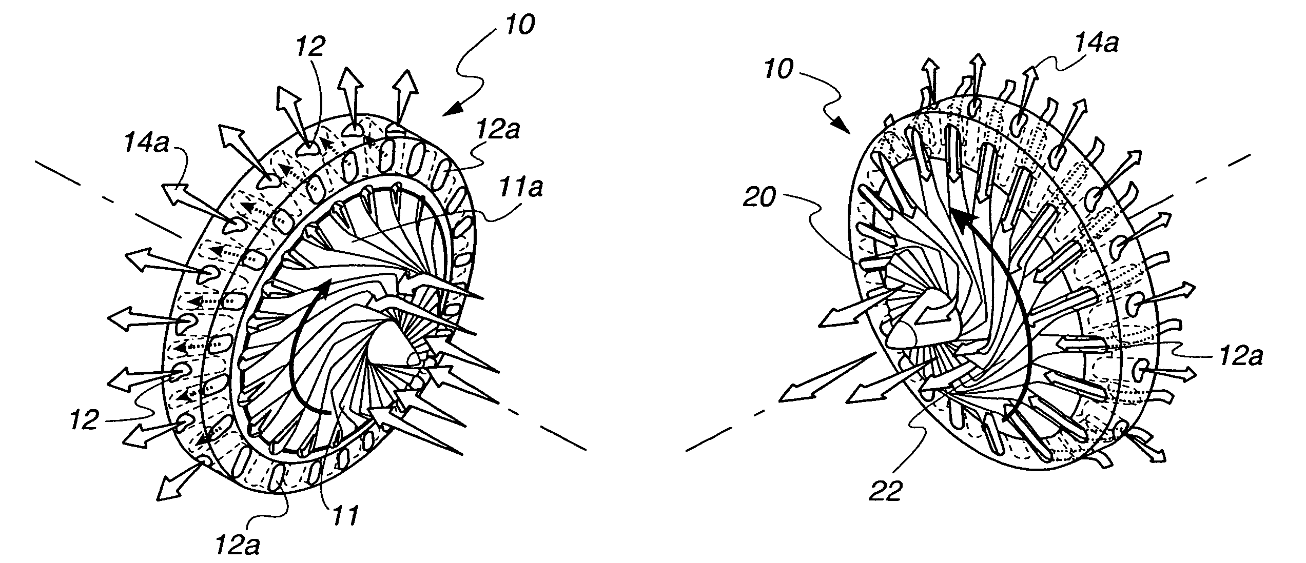
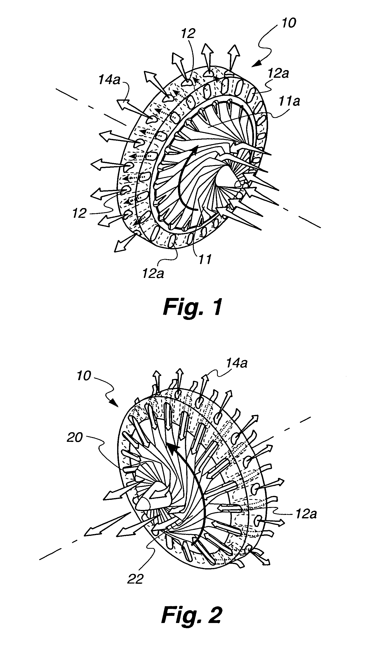
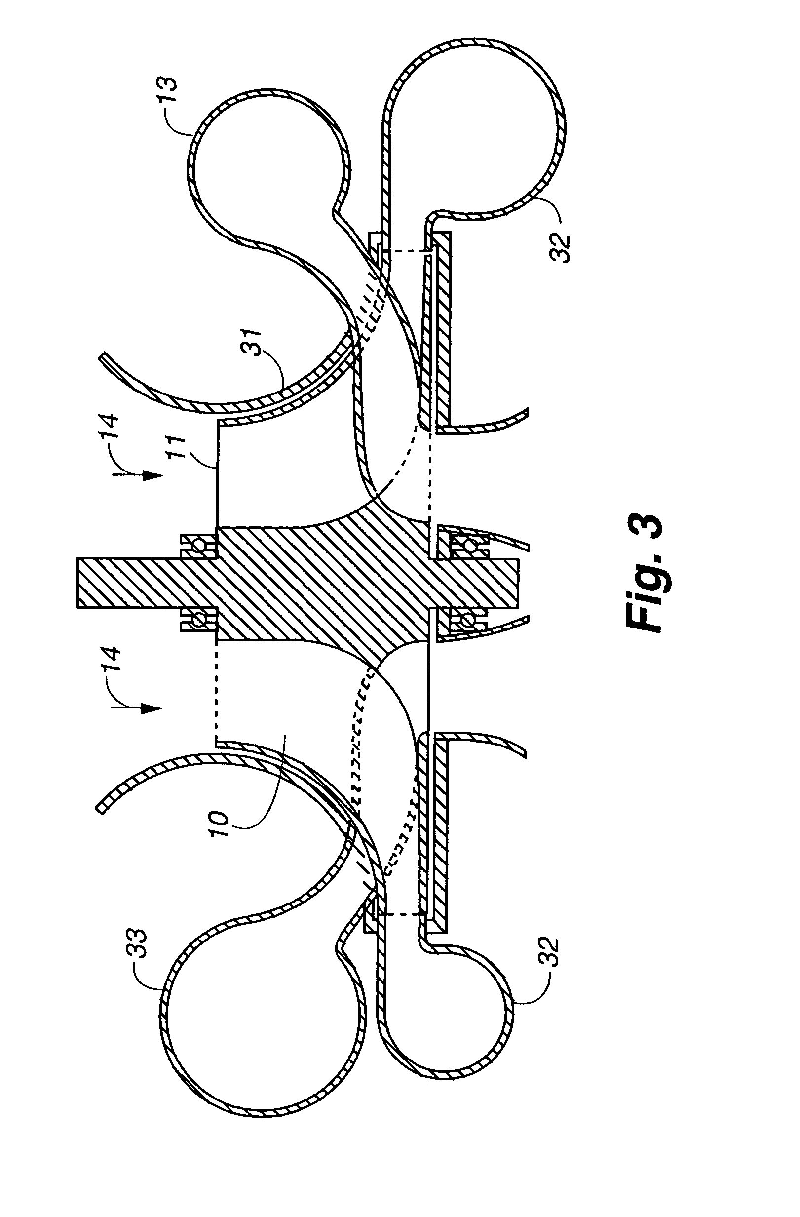
[0023]Referring now to FIG. 1, there can be seen a perspective view of an embodiment of rotor 10 showing its intake side featuring radial compressor / pump 11 having fins 11a. Fins 11a may either compress incoming fluid flow 14 in some applications, or simply pump incoming fluid flow 14 in other applications, and direct it into compressor ducts 12 that also serve to cool radial turbine blades 12a. In some applications, incoming fluid flow 14 exchanges heat with radial turbine blades 12a as it passes through them. Compressed fluid flow 14a flows out of rotor 10 as shown and into a volute (see FIG. 3) and eventually, after being heated in some applications, compressed fluid flow 14a is directed back through turbine blades 12a of rotor 10.

[0024]Those having skill in this art will readily understand that rad...


PUM


Abstract

A rotor for use in turbine applications has a radial compressor / pump having radially disposed spaced apart fins forming passages and a radial turbine having hollow turbine blades interleaved with the fins and through which fluid from the radial compressor / pump flows. The rotor can, in some applications, be used to produce electrical power.

Description

FIELD OF THE INVENTION[0001]The present invention generally relates to turbines and more specifically to rotors used in turbine applications. This invention was made with Government support under Contract No. W-7405-ENG-36 awarded by the U.S. Department of Energy. The Government has certain rights in the invention.BACKGROUND OF THE INVENTION[0002]Since the earliest use of water to turn a wheel, turbines have provided needed mechanical action for myriad functions. In modern times, turbines are used to generate electricity, power jet aircraft and increase the power of automobiles using turbochargers, as well as in many other uses. Many turbine applications use two rotors on the same shaft so that one turbine powers the other. When the rotors are on a fairly long connecting shaft, problems of balance, shaft whip, and multiple vibrational modes become exacerbated. These problems can cause various troubles up to the failure of the machine.[0003]Smaller turbine engines are now being used ...

Claims


Application Information

Patent Timeline
Patent Type & Authority Patents(United States)
IPC IPC(8): F04B17/00F04B35/00
CPCF02C3/045F04D25/045F04D13/043F02C3/073
Inventor PLATTS, DAVID A.
Owner LOS ALAMOS NATIONAL SECURITY
Why Eureka
Try Eureka