Hinge system for regulating knee joint flexion and extension

a technology of knee joint flexion and extension, which is applied in the field of hinge mechanisms for knee braces, can solve the problems of reducing the likelihood of the user's knee joint being properly rehabilitated, most contemporary knee brace hinge mechanisms fail to possess sufficient adjustability, and most conventional hinge mechanisms are not able to provide the precise simulation of knee joint movement as described above or control the range of knee joint motion. to achieve the effect of preventing re-injury

Active Publication Date: 2006-05-16
OSSUR HF
View PDF93 Cites 29 Cited by
  • Summary
  • Abstract
  • Description
  • Claims
  • Application Information

AI Technical Summary

Benefits of technology

[0009]The present invention specifically addresses and alleviates the above-referenced deficiencies associated with the use of the knee brace hinge mechanisms of the prior art. More particularly, the present invention comprises an improved hinge system for a knee brace which is sized and configured to simulate the movement of a knee joint while

Problems solved by technology

However, most conventional hinge mechanisms typically fail to provide the precise simulation of knee joint movement as described above or control the range of knee joint motion.
Such deficiency inevitably decreases the likelihood of the user's knee joint from being properly re

Method used


Image

  • Hinge system for regulating knee joint flexion and extension
  • Hinge system for regulating knee joint flexion and extension
  • Hinge system for regulating knee joint flexion and extension

Examples


Embodiment Construction

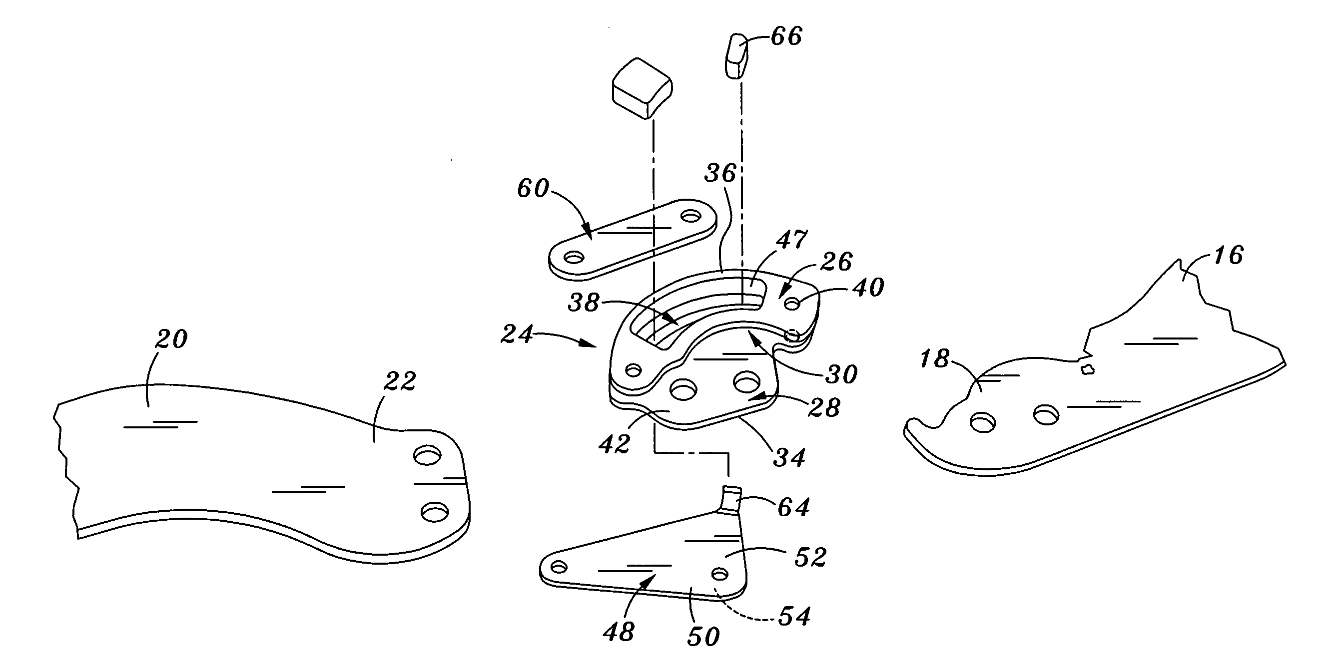
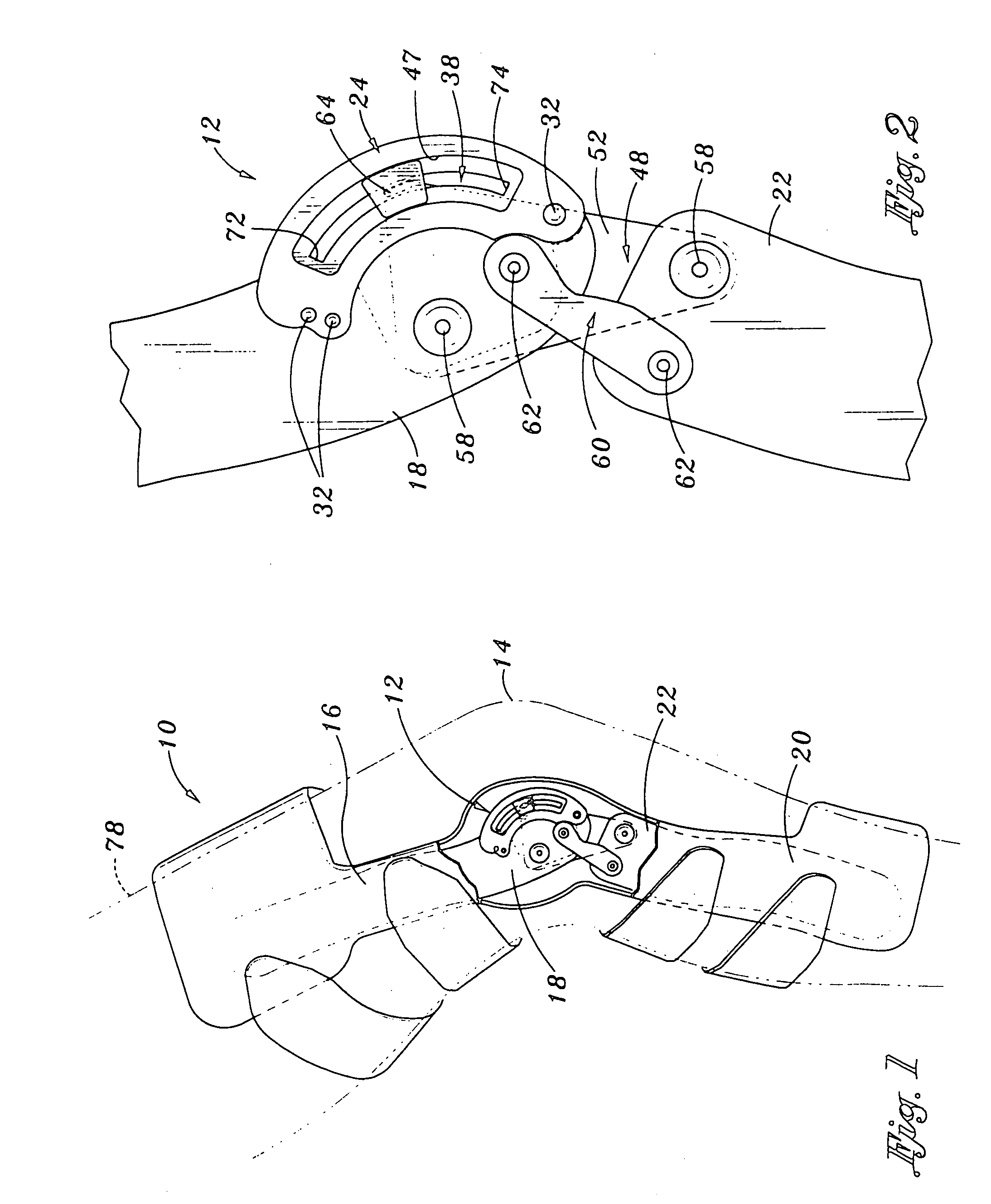
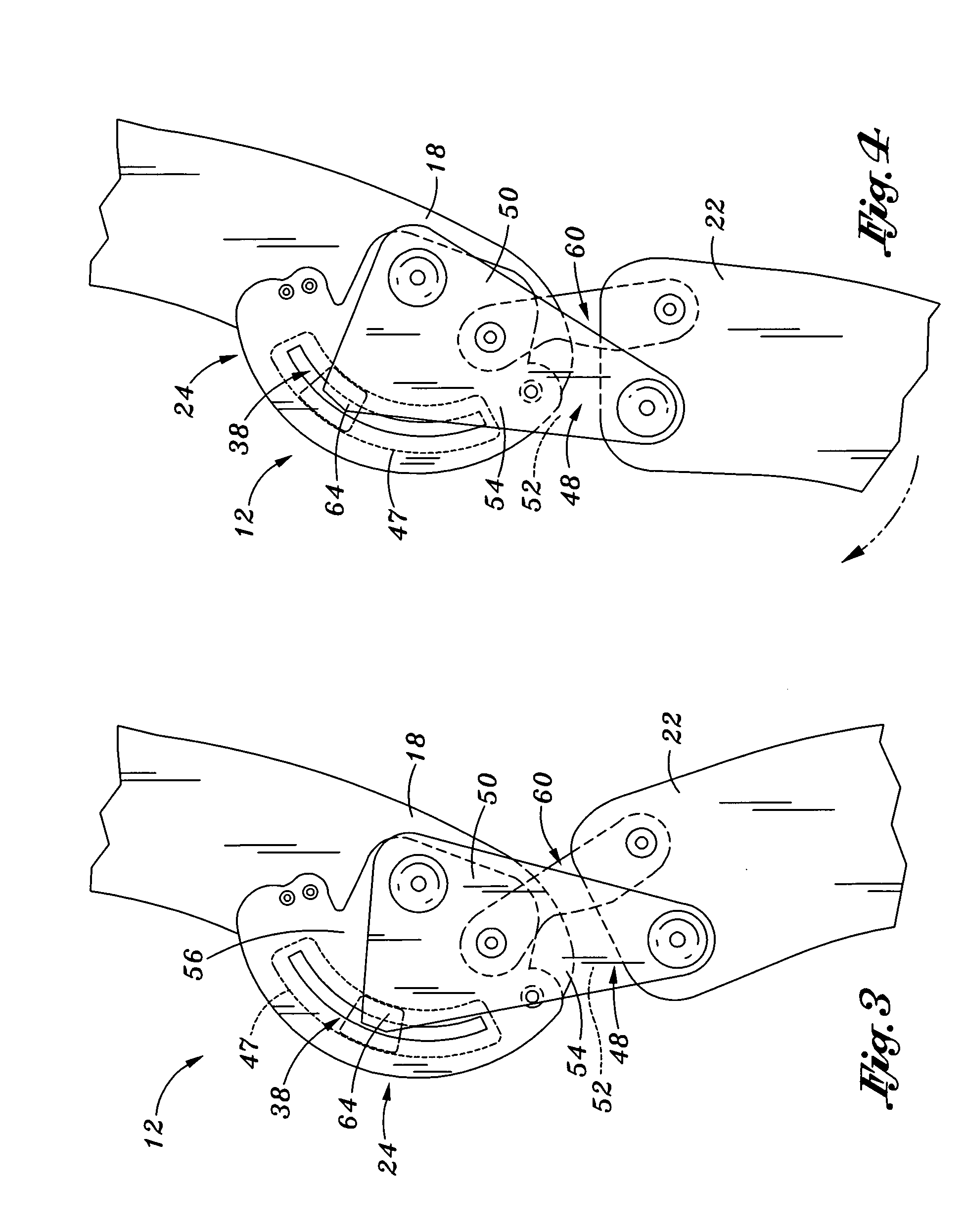
[0031]Referring now to the drawings wherein the showings are for purposes of illustrating preferred embodiments of the present invention only, and not for purposes of limiting the same, FIG. 1 illustrates a knee brace 10 constructed in accordance with a preferred embodiment of the present invention. As indicated above, the present knee brace 10 includes a unique hinge system 12 which simulates the movement of a user's knee joint 14, while being capable of regulating its flexion and extension within a number of prescribed ranges of motion. This ability to simulate and regulate the knee joint movements within a selected optimal range of motion helps to rehabilitate an injured knee joint 14 and may further prevent re-injury of the same due to hyper-extension and / or flexion.

[0032]Referring more particularly to FIGS. 2 and 5, the knee brace hinge system 12 of the present invention may be utilized in conjunction with various knee braces. Types of knee braces that are compatible with the p...


PUM


Abstract

A hinge system for a knee brace features a flexion-extension regulating device which is adapted to engage an end portion of the knee brace's upper strut. An elongated main slot is formed through the regulating device to provide a fixed boundary for limiting range of motion. A motion limiting member is connected to the regulating device and is further adapted for connection to an end portion of the knee brace's lower strut. The motion limiting member includes a motion limiter that is disposed within the main slot. The motion limiter is caused to move therealong when the upper and lower struts pivot about a user's knee joint. By confining the motion limiter within the fixed boundary formed by the main slot, the hinge system ensures that the user's knee joint flexes and extends within the prescribed range of motion.

Description

CROSS-REFERENCE TO RELATED APPLICATIONS[0001]The present application claims priority to U.S. Provisional Application Ser. No. 60 / 437,059 entitled HINGE SYSTEM FOR REGULATING KNEE JOINT FLEXION AND EXTENSION filed Dec. 30, 2002.STATEMENT RE: FEDERALLY SPONSORED RESEARCH / DEVELOPMENTBACKGROUND OF THE INVENTION[0002]The present invention relates generally to hinge mechanisms for knee braces, and more particularly to an improved hinge system for a knee brace which is adapted to simulate the movements of a knee joint while regulating its flexion and extension within a plurality of prescribed ranges of motion.[0003]A knee joint is essentially comprised of two joints, namely, lateral and medial joints, which are positioned between the femur and tibia. The primary movements of the knee joint are flexion (rearward rotational movement of the tibia relative to the femur) and extension (forward rotational movement of the tibia relative to the femur). The flexion and extension movements of the kn...

Claims


Application Information

Patent Timeline
IPC IPC(8): A61F5/00A61F5/01
CPCA61F5/0123A61F2005/0137A61F2005/0167A61F2005/0146A61F2005/0144
Inventor CASTILLO, JAMES D.CASTILLO, MIKELEITNER, BERNHARD
Owner OSSUR HF
Why Eureka
Try Eureka