Well-to-well tomography

a well-to-well and tomography technology, applied in the field of well-to-well tomography, can solve the problem of adverse effects of seismic signal reflected from the subsurface layer under the seismic receiver

Active Publication Date: 2006-05-16
SHELL USA INC
View PDF20 Cites 71 Cited by
  • Summary
  • Abstract
  • Description
  • Claims
  • Application Information

AI Technical Summary

Problems solved by technology

The signal reflected from the subsurface layer under the seismic receiver is adversely affected by the presence of the complex transmission medium.

Method used


Image

  • Well-to-well tomography
  • Well-to-well tomography
  • Well-to-well tomography

Examples


Embodiment Construction

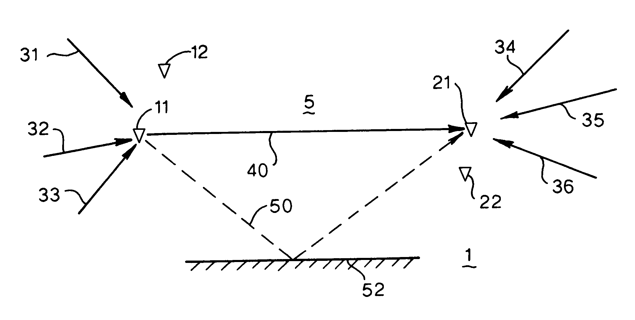
[0021]FIG. 1 shows a horizontal section through an underground formation 1. Two boreholes (10 and 20 ) are drilled through the underground formation, and in the parts of the borehole that are adjacent to a zone 5 in the underground formation that is to be studied, seismic receivers are arranged.

[0022]A first set of seismic receivers i, wherein i is 11 and 12 has been arranged in the first borehole 10 and a second set of seismic receivers j, wherein j is 21 and 22 has been arranged in the second borehole 20. The second borehole is spaced apart from the first borehole.

[0023]Having positioned the seismic receivers 11, 12, 21 and 22, the method of the present invention continues with selecting at least one pair of seismic receivers, wherein each pair of seismic receivers consists of a seismic receiver i of the first set and a seismic receiver of the second set j. Let us take as an example the pair consisting of the seismic receivers 11 and 21.

[0024]For the pair(s) of seismic receivers s...


PUM


Abstract

A method of obtaining a spatial model of a property of part of a subsurface formation located between underground seismic receivers in which at least two sets of pairs of seismic receivers are utilized and one pair of receivers is used to record a signal from a seimic source and obtaining a response by solving (s11(−t){circle around (x)}s21(t))=r11,21(t){circle around (x)}(s11(−t){circle around (x)}s21(t)), wherein the symbol {circle around (x)} denotes convolution and wherein s11(−t) is the time-reverse of the signal s11(t). A path-related attribute is selected from transmission response r11,21(t) that corresponds to the property of the subsurface formation and a tomographic reconstruction technique is applied to the path-related attribute to obtain the spatial model of the property of part of the subsurface formation.

Description

PRIORITY CLAIM[0001]The present application claims priority on U.S. Provisional Application No. 60 / 526,060, filed Dec. 1, 2003.BACKGROUND OF THE INVENTION[0002]The present invention relates to a method of well-to-well tomography, which is a method to obtain geologic details of an underground formation from sound waves traversing the formation. In particular well-to-well tomography is a method of obtaining a spatial model of a property of part of a subsurface formation located between underground seismic receivers.[0003]In a way, the formation between seismic receivers can be regarded as a complex transmission medium in the sense as referred to in Applicant's International patent application publication No. 03 / 023450. This publication deals with a method of seismic imaging a subsurface formation, wherein a complex transmission medium is present between a set of seismic sources and a set of seismic receivers. The method described in this publication serves to reduce the adverse effect...

Claims


Application Information

Patent Timeline
Patent Type & Authority Patents(United States)
IPC IPC(8): G01V1/40G01V1/42
CPCG01V1/42
Inventor CALVERT, RODNEY WILLIAM
Owner SHELL USA INC
Why Eureka
Try Eureka