Direct tomographic reconstruction

a tomographic reconstruction and reconstruction technology, applied in the field of medical imaging systems and methods, can solve the problems of unsuitable images, large axial blurring, and unsuitable images, and achieve the effects of reducing noise, reducing noise, and small effect on the resolution of final images

Inactive Publication Date: 2006-08-01
GE MEDICAL SYST ISRAEL
View PDF15 Cites 24 Cited by
  • Summary
  • Abstract
  • Description
  • Claims
  • Application Information

AI Technical Summary

Benefits of technology

[0054]In a preferred embodiment of the invention a smoothing, median or other noise reducing filter is applied to the data generated by a given iteration prior to the application of a subsequent iteration. When a filter of this type is so applied the effect on the resolution of the final image is small, since subsequent iterations “correct” the smoothing, while the noise level of the image is reduced. Alternatively, a band enhancing filter, such as a METZ filter which also reduces noise can be used.
[0055]As indicated above, if the LOF can be determined, as for example by consideration of the position of the event on the detector and the collimator angle for SPECT and by consideration of the focal spot of the x-ray tube and the point of detection of the x-ray photons (for X-ray CT tomography), the OSEM algorithm of the present invention is applicable. Furthermore, since the method of the present invention does not require the construction of sinograms and / or slice data, it allows for direct reconstruction of three dimensional images from cone beam based data. Since the method is tolerant of incomplete data sets, cone beam data (generated from either single or multifocal sources) can be used, and used in an efficient manner to generate three dimensional data. Furthermore, fan beam data (either single or multifocal sources) can be used without binning and without the need for forming sinograms.

Problems solved by technology

One of the major problems with this reconstruction system is the “blurring” of events in the direction perpendicular to the plane of the rings.
This blurring, if not reduced, results in an image which is unsuitable, for diagnostic purposes.
If events cause coincidence detection in widely spaced rings, they naturally cause greater axial blurring.
This rebinding reduces the axial blurring, however, it increases the image noise.
However, this method, while theoretically possible, requires very large amounts of computation in order to reach satisfactory results, so that it has not been implemented commercially.
However, ring type PET systems are not of general utility.
For this reason and, to a lesser extent, because of its geometry, such a system is useful only for PET and cannot be used for other NM applications such as for acquiring planar images and for SPECT.
Neither the EM nor OSEM algorithms are easily applied to systems of planar detectors.
However, this is not practical.
If an attempt is made to use a pair of opposed planar detectors (of the type normally used for planar or SPECT imaging), rotating about the subject, to acquire data for constructing PET images using EM (or OSEM) techniques, the amount of data which is acquired is reduced, as compared to the ring type PET system, making the planar system impractical.
Thus, for such a device, the normal binning procedure according to a fixed set of a very large number of bins is impractical and results in excessive calculation.
Also, with such sparse data the results can be expected to be noisy.
The prior art does not teach any way to combine the advantages of the OSEM system with the higher intrinsic resolution of planar detectors.

Method used


Image

  • Direct tomographic reconstruction
  • Direct tomographic reconstruction
  • Direct tomographic reconstruction

Examples


Embodiment Construction

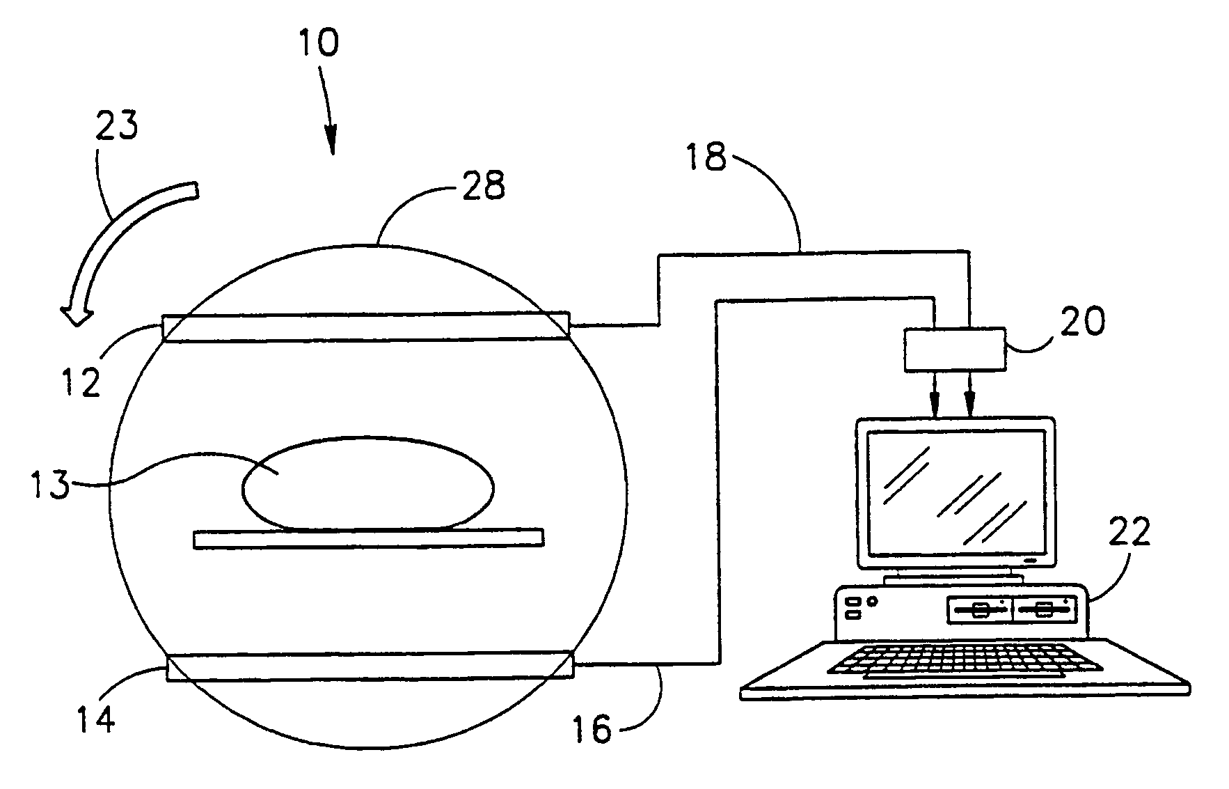
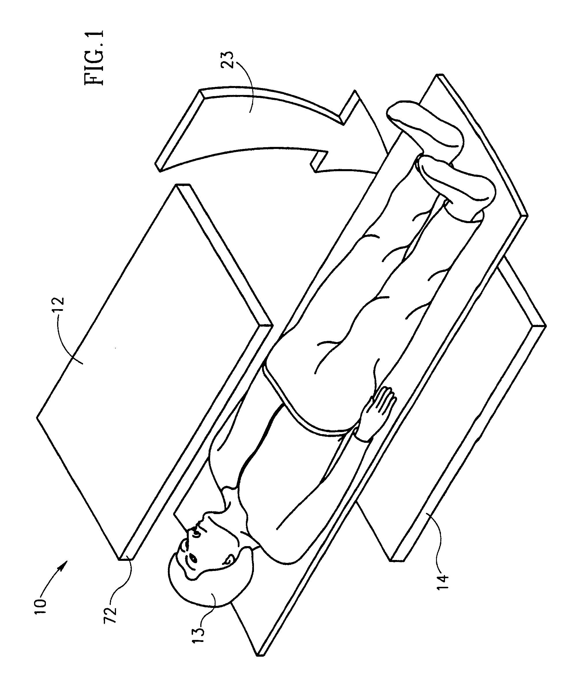
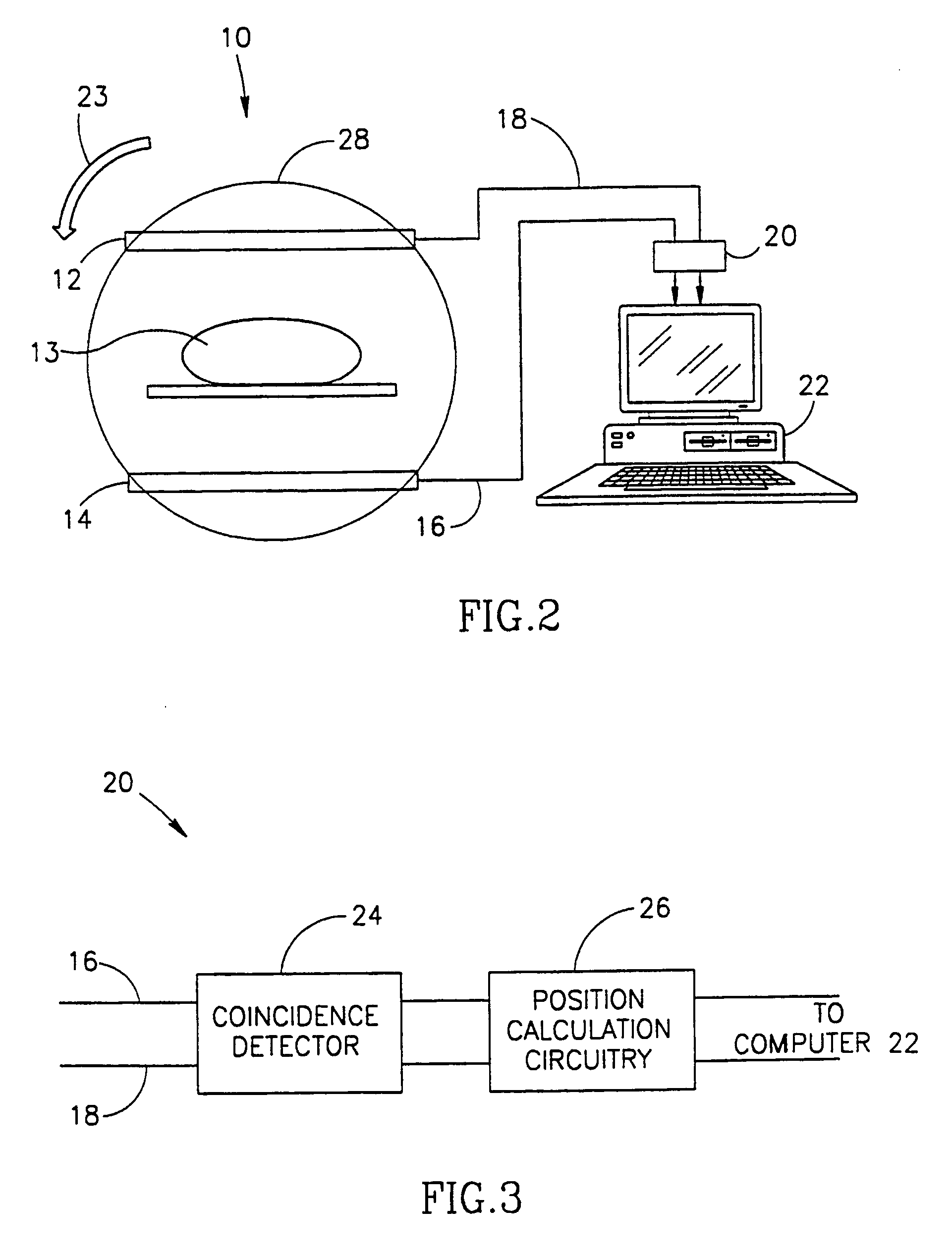
[0100]FIGS. 1 and 2 are simplified perspective and cross-sectional representations of a PET imaging and reconstruction system 10 in accordance with a preferred embodiment of the invention.

[0101]PET system 10, in the preferred embodiment shown in FIGS. 1 and 2 comprises a pair of area detectors 12 and 14 placed on opposite sides of a subject 13 who has been previously injected with a material which decays producing a pair of photons which are ejected in opposite directions. Area detectors 12, 14 can be any type of area detectors known in the art. However, in a preferred embodiment of the invention, the area detectors comprise a large scintillator crystal which emits light when a gamma ray photon is absorbed by the crystal. A series of photomultipliers, preferably arranged in a hexagonal configuration are attached to and view the crystal and produce electrical signals which are proportional to the amount of light which reaches the photomultiplier. The position on the crystal at which ...


PUM


Abstract

A method of reconstructing tomography images comprising: acquiring data on individual radiation events; distributing a weight of the individual radiation events along a line of flight associated with the event determined from the acquired data; and iteratively reconstructing the image based on the individually reprojected data.

Description

RELATED APPLICATION[0001]This application is a US National filing of PCT Application PCT / IL97 / 00128, filed Apr. 17, 1997.FIELD OF THE INVENTION[0002]The present invention relates to the field of medical imaging systems and methods and particularly to methods and apparatus for the acquisition of tomographic data, especially PET data and the reconstruction of three-dimensional images based on the data.BACKGROUND OF THE INVENTION[0003]Gamma cameras known in the art of Nuclear Medicine (NM) imaging produce tomographic images that are indicative of physiological activity. Such cameras receive radiation that is emitted by radioisotope markers or tracers, which are introduced into the body of a subject and are taken up by an organ of the body in proportion to the physiological activity of interest. The radiation emitted is generally received by a scintillator / detector system, which produces electrical signals responsive to photons of the radiation incident thereon. The signals are processe...

Claims


Application Information

Patent Timeline
Patent Type & Authority Patents(United States)
IPC IPC(8): G06K9/00G06T11/00
CPCG06T11/006G06T2211/424
Inventor LEVKOVITZ, RONZIBULEVSKY, MICHAELFALIKMAN, DIMITRYBERLAD, GIDEON
Owner GE MEDICAL SYST ISRAEL
Why Eureka
Try Eureka