X-ray CT apparatus

a technology of ct apparatus and ct, which is applied in the field of x-ray ct apparatus, can solve the problems of adjusting means and the drawback of conventional methods, and achieve the effects of improving body axial resolution, and reducing the risk of

Inactive Publication Date: 2006-05-16
HITACHI MEDICAL CORP
View PDF6 Cites 3 Cited by
  • Summary
  • Abstract
  • Description
  • Claims
  • Application Information

AI Technical Summary

Benefits of technology

[0021]In accordance with the present invention, the slice width can be variably changed. Also, since the slice width can be made narrow, body axial r

Problems solved by technology

As previously described, the conventional method owns suc

Method used


Image

  • X-ray CT apparatus
  • X-ray CT apparatus
  • X-ray CT apparatus

Examples


Embodiment Construction

[0034]Referring now to the accompanying drawings, preferable embodiment modes of an X-ray CT apparatus according to the present invention will be described.

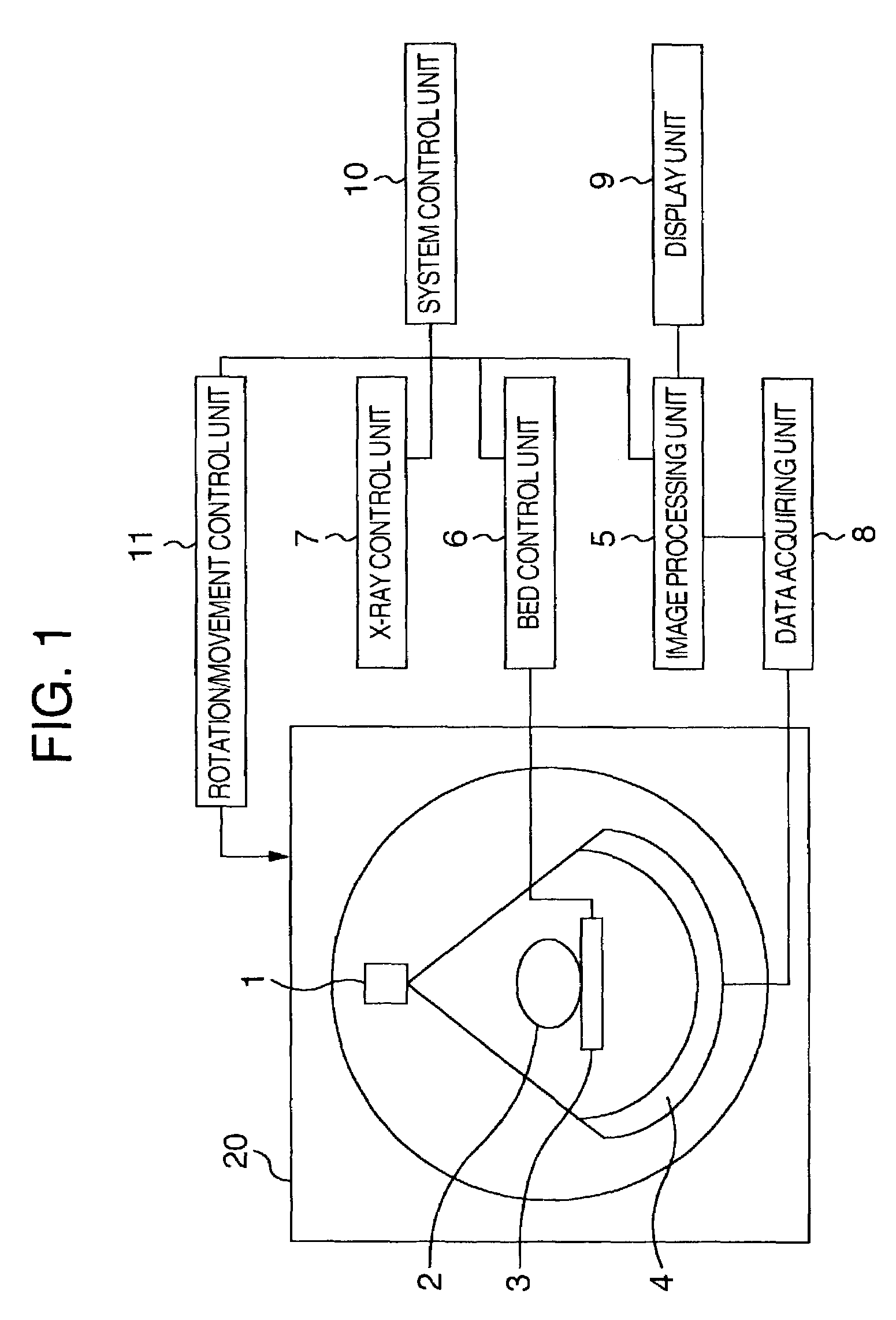
[0035]FIG. 1 is a block diagram for showing a structure of an X-ray CT apparatus according to the present invention.

[0036]In an X-ray CT apparatus 20, fan-beam X-rays (normally, being obtained via a collimator from X-ray source, will be referred to as an “X-ray source” containing this collimator) are irradiated from an X10 ray source 1 onto an object 2 to be examined located on a bed 3, and then, an amount of X-rays which have penetrated through the object 2 is detected by an X-ray detector 4 which is arranged in a fan shape and positioned opposite to the X-ray source 1. While both the X-ray source 1 and the X-ray detector 4 are rotated around the object 2 in a constant time period, a data acquiring unit 8 acquires an X-ray transmission amount data which is detected by the X-ray detector 4. With respect to this acquired data, a t...


PUM


Abstract

Both an X-ray source and an X-ray detector are moved in a pitch which is smaller than a width of this detector. Since both the X-ray source and the X-ray detector are rotated by an angle of 360° within one move distance, a CT measurement is carried out. An X-ray detection amount of a slice width narrower than an X-ray effective detection width is calculated based upon the X-ray detection amount measured in the above-described manner.

Description

TECHNICAL FIELD[0001]The present invention relates to an X-ray CT apparatus for acquiring tomographic images having variable slice thicknesses.BACKGROUND ART[0002]In an X-ray CT apparatus, while both an X-ray source and an X-ray detector positioned opposite to the X-ray source are rotated around an object to be examined, X-ray beams (fan beams) are irradiated from the X-ray source in a fan shape, and then, an amount of X-rays which have penetrated through the object is detected by the X-ray detector. Transmission X-ray amount data detected by the X-ray detector is acquired, and a tomographic image is reconstructed based on this acquired data by a reconstructing means.[0003]A fan-shaped X-ray beam owns a certain extended projection angle and a certain width. This width will be referred to as a “beam slice width.” Since a width of an X-ray detector is made equal to this beam slice width, a slice width of a tomographic image is made coincident with the beam slice width.[0004]Convention...

Claims


Application Information

Patent Timeline
IPC IPC(8): A61B6/00A61B6/03
CPCA61B6/032
Inventor TSUJI, MASAHIRO
Owner HITACHI MEDICAL CORP
Why Eureka
Try Eureka