Integrated flat panel workstation system

Inactive Publication Date: 2006-05-23
THOMAS WHITE +1
View PDF16 Cites 48 Cited by
  • Summary
  • Abstract
  • Description
  • Claims
  • Application Information

AI Technical Summary

Benefits of technology

[0010]It is, therefore, an object of the present invention to provide a compact, functional, ergonomically correct and convenient multi-use

Problems solved by technology

The “L” shaped configuration limits the work area, as well as contributing to a setup problem for the student and teacher.
The highly directional images and lower light e

Method used


Image

  • Integrated flat panel workstation system
  • Integrated flat panel workstation system
  • Integrated flat panel workstation system

Examples


Embodiment Construction

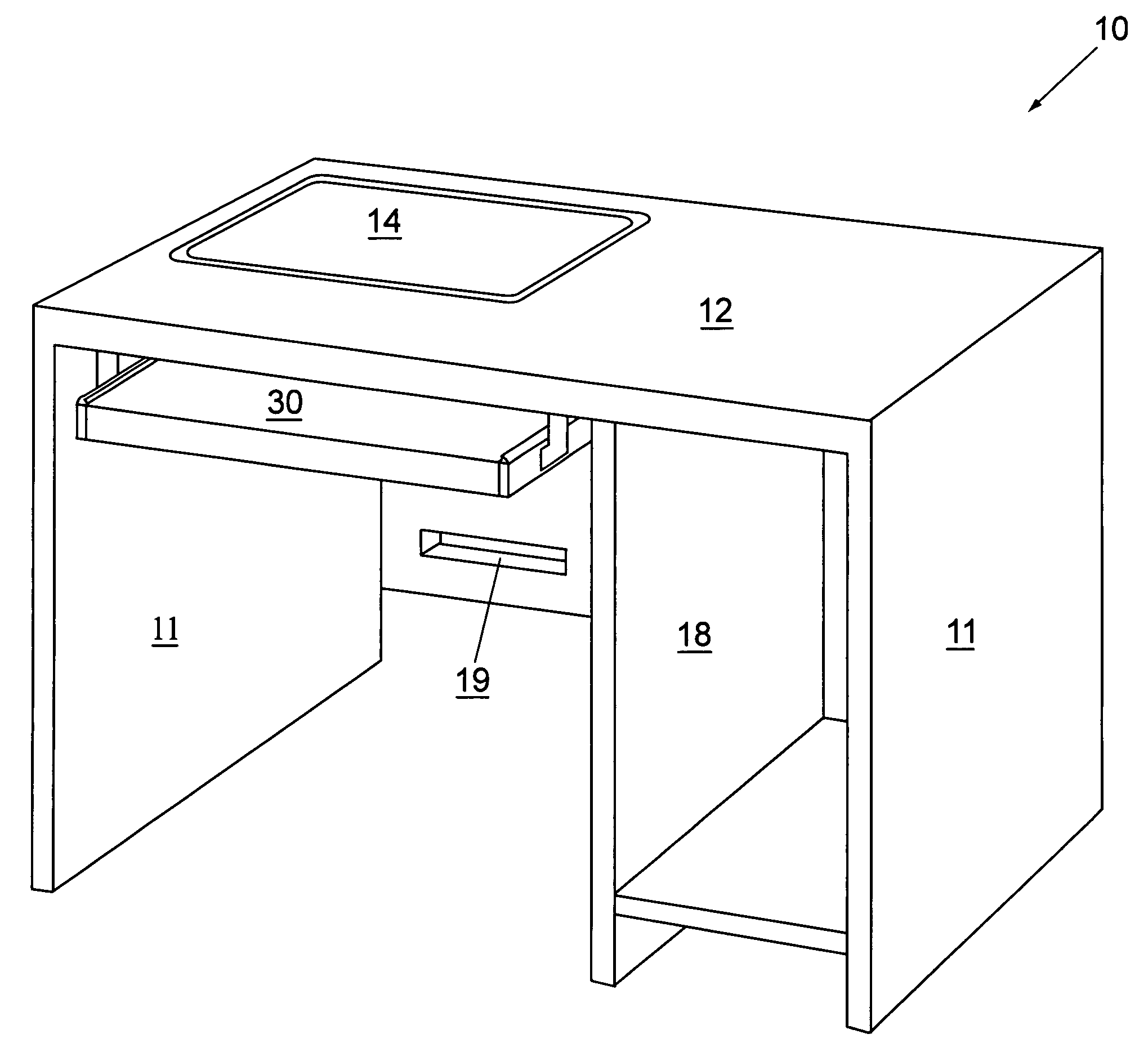
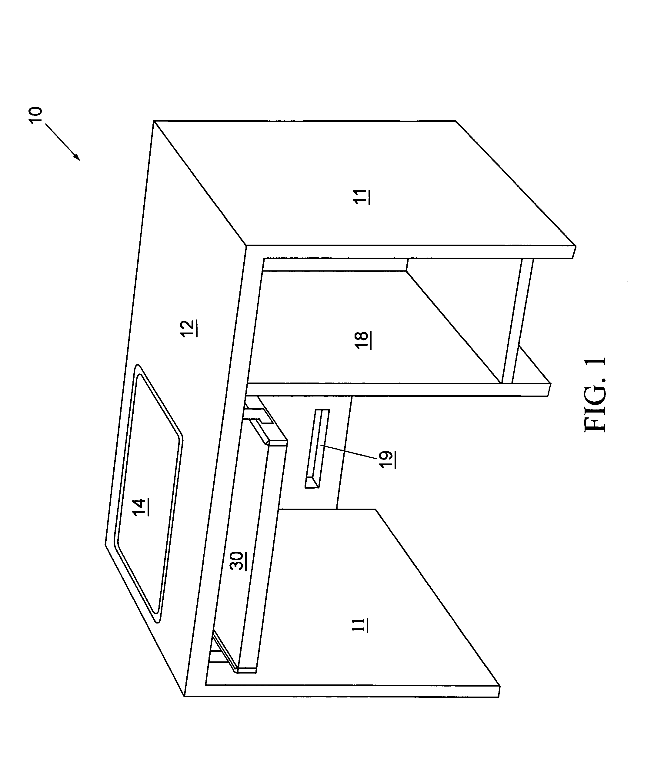
[0028]FIG. 1 is a front perspective view of a computer workstation 10 according to a preferred embodiment of the present invention. The computer workstation 10 generally includes a sliding input device platform 30 and a pivoting support panel 14 in a work surface 12, the support panel 14 being adapted to support an integrated flat panel LCD 60 (see FIG. 5) mounted thereon. In accordance with the present invention, a mechanism is provided (described below) by which extension of the input device platform 30 into a working position (see FIG. 5) automatically and gently rotates the flat panel LCD 60 to a viewable position in front of a user. Additionally, the rotation may automatically turn the LCD 60 on by means of a gravity switch.

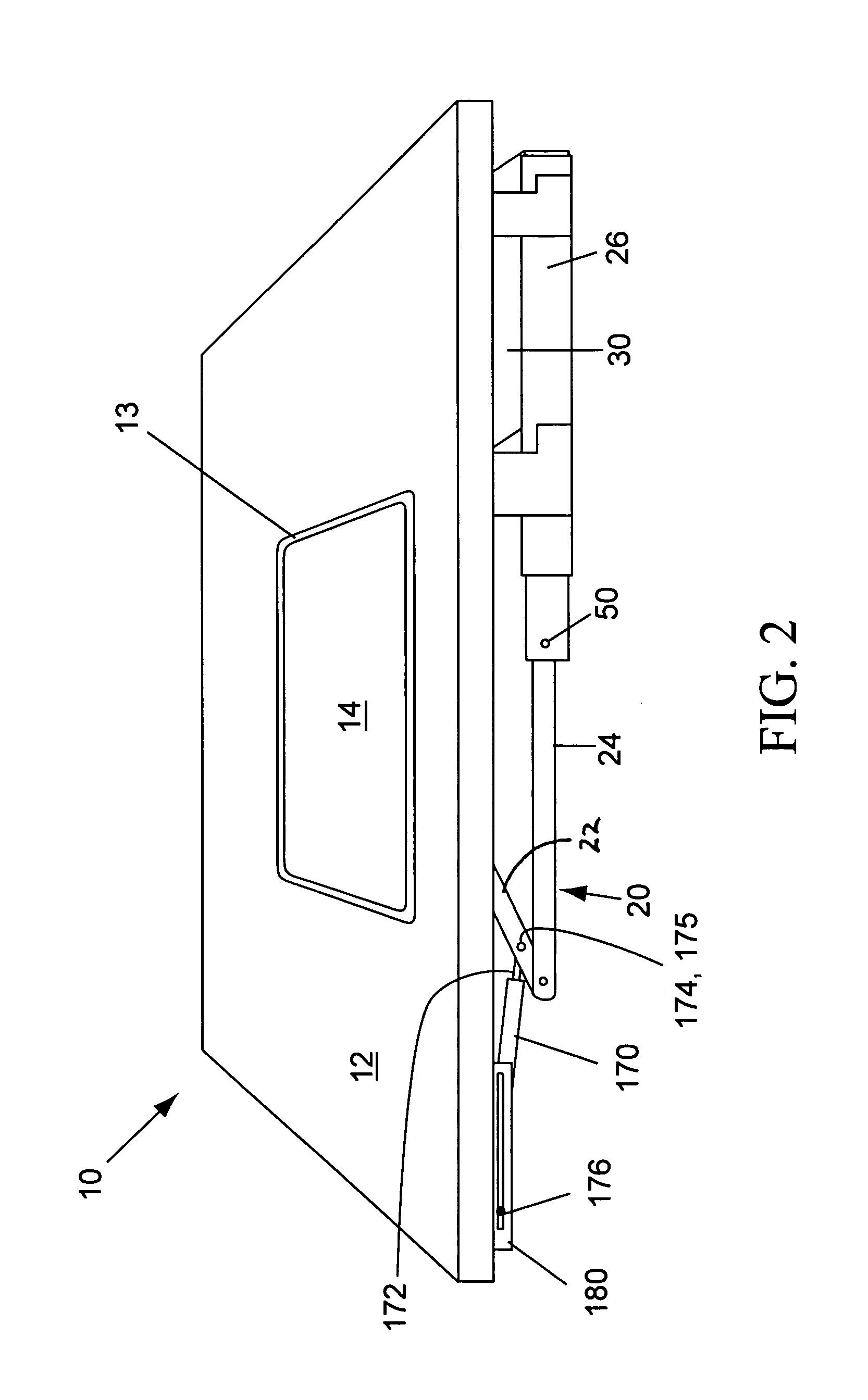
[0029]FIGS. 2–4 are side perspective views of the computer workstation 10 with the support panel 14 and integrated flat panel LCD 60 shown, respectively, in closed, partially open, and fully open positions, according to a preferred embodiment of the present ...


PUM


Abstract

A computer workstation having a desktop/work surface defined by a central aperture and a pivoting liquid crystal display (LCD) support panel mounted on pivot shafts in the aperture. In addition, a sliding input device platform is mounted on telescoping roller brackets underneath the front edge of the work surface. Lever arms are rotatably engaged with the pivot shafts and are linked to the roller brackets. The lever arms automatically pivot the LCD support panel to an upright position upon extension of the input device platform, and vice versa, and a hydraulic damper brings the LCD support panel to a safe, gentle stop. Aa mercury switch turns the LCD on and off automatically upon opening or closing. Two or more such LCD support panels and associated hardware can be included in a single desktop/work surface for a computer training and/or conferences.

Description

CROSS-REFERENCE TO RELATED APPLICATIONS[0001]The present application derives priority from U.S. provisional application No. 60 / 436,515 for “INTEGRATED FLAT PANEL DESK SYSTEM; Filed: 27 Dec. 2002.BACKGROUND OF THE INVENTION[0002]1. Field of the Invention[0003]The present invention relates to computer workstations and, more particularly, to a computer workstation having a pivoting working surface that exposes an integrated flat panel liquid crystal display (LCD).[0004]2. Description of the Background[0005]Of the many varieties of commercially-available computer workstations, some are designed to enclose the computer to offer a multi-use work surface, conserve space, provide data privacy, protect the equipment and wiring, and maintain aesthetics. Examples of typical applications include educational and medical institutions, commercial offices, and retail, hospitality, government, and military entities. In these and other situations, it is desirable to incorporate the computers into the...

Claims


Application Information

Patent Timeline
IPC IPC(8): A47B37/00A47B21/00
CPCA47B21/0073A47B2021/0076
Inventor KORBER, JEFFREYSTENGEL, PETERBABCOCK, JAMES
Owner THOMAS WHITE
Why Eureka
Try Eureka