
Material feeding container for two-cylinder thick matter pumps

Inactive Publication Date: 2006-05-23
PUTZMEISTER CONCRETE PUMPS GMBH
View PDF9 Cites 6 Cited by
  • Summary
  • Abstract
  • Description
  • Claims
  • Application Information

AI Technical Summary

Benefits of technology

[0006]Beginning therewith, it is the task of the invention to improve the known material supply containers of the above described type in such a manner that a simple servicing of the material supply container is made possible and nevertheless a stable construction is ensured and dead space inside the container is avoided.
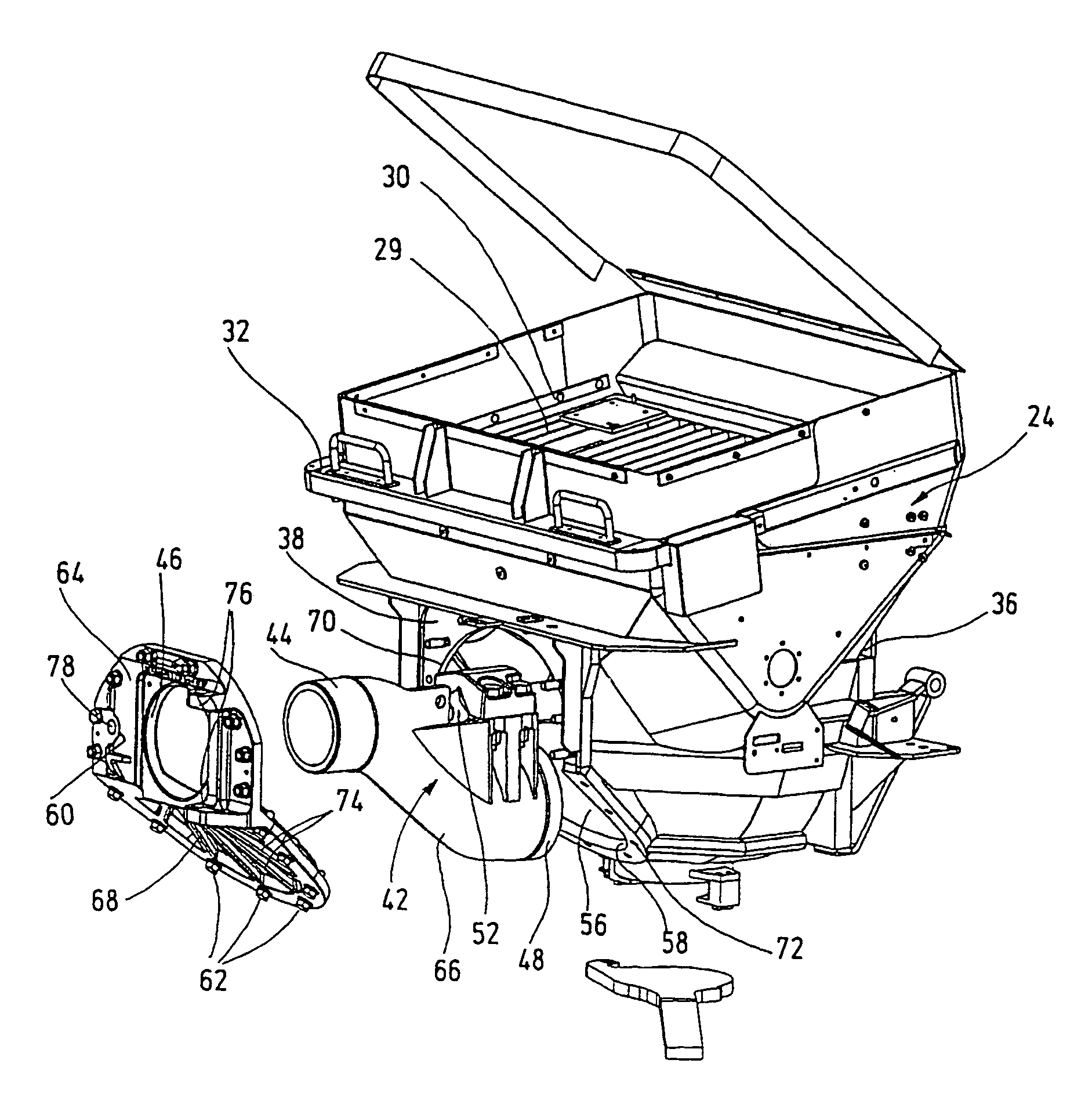
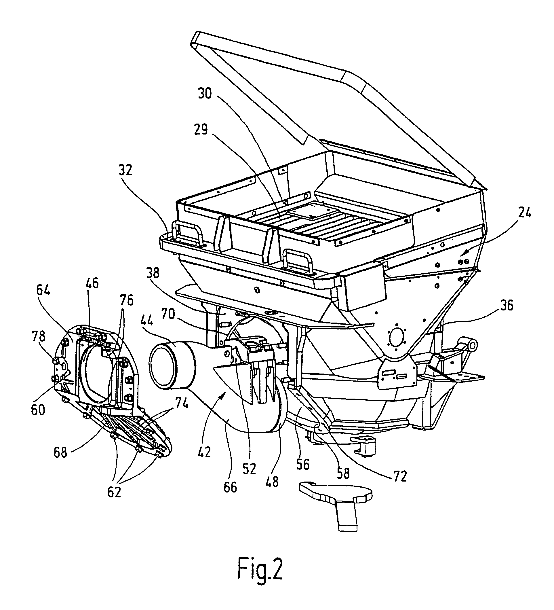
[0008]The inventive solution is based upon the idea that the service opening is a cutout in the rear wall bordered by a circumferential edge, and that the maintenance opening can be closed with a cover plate, which has a top cover plate part that is oriented perpendicular to the swivel axis of the S-pipe and includes the feed-through opening for the S-pipe, and a bottom cover plate part that forms an inclined bottom part and is connected to said top cover plate part substantially parallel to an S-pipe segment extending obliquely downward. Therein the service opening must be sufficiently large that the S-pipe can pass through it. Although the service opening is thus relatively large, the circumferential edge ensures a sufficient shape-stability. A further improvement in this respect results when the cover plate is comprised of two cover parts oriented diagonally to each other. The lower, diagonally oriented cover plate part runs close to the slanted S-pipe segment, so that the production of a dead space, in which concrete can deposit, is substantially avoided.

Problems solved by technology

Since an agitator is additionally provided in the inside of the container, the dismantling and reinstallation of the pipe switch through the material supply opening is accomplished with difficulty.
In this design however the stability of the material supply container suffers.

Method used


Image

  • Material feeding container for two-cylinder thick matter pumps
  • Material feeding container for two-cylinder thick matter pumps
  • Material feeding container for two-cylinder thick matter pumps

Examples


Embodiment Construction

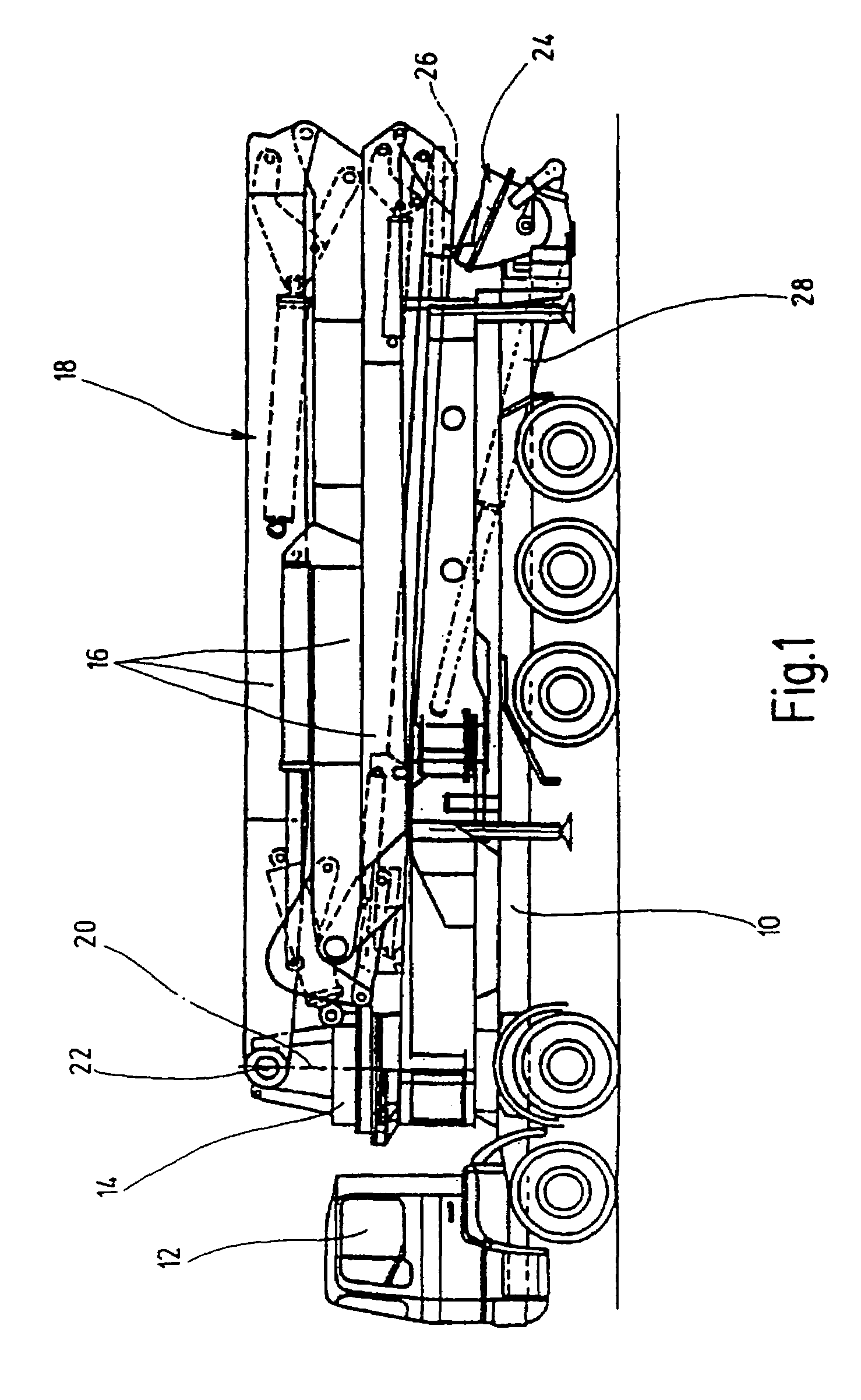
[0017]The mobile concrete pump is comprised essentially of an undercarriage 10 in the form of a truck chassis with driver cab 12, with a mast block or base block 14 provided in the forward part of the undercarriage 10, to which a distribution boom 18 is connected comprised of multiple foldable boom arms 16 rotatable about a vertical axis 20 and pivotable about a horizontal axis 22, a material supply container 24 located in the vicinity of the rearward end of the vehicle undercarriage 10 and a concrete pump 28 connected on the suction side with the material supply container 24 and on the pressure side with a conveyor line 26 extending along the distribution boom 18. The material supply container 24 includes a diagonally upward oriented material intake opening 30 covered with a grate 29, which is bordered by a flange-like opening 32.

[0018]The material supply container 24 is a component of a two-cylinder thick matter pump 28, wherein the conveyor cylinders 31 are in communication with ...


PUM


Abstract

The invention relates to a material feeding container for two-cylinder thick matter pumps. The material feeding container (24) has a material supply opening (30) oriented upward, two feed cylinder openings (34) arranged in the front wall (36) of the container and a transfer tube having the shape of an S-tube (42), which is arranged inside the container with its input end (48) swiveling in an alternating manner in front of the feed cylinder openings (34) and mounted on the output side in a feed-through opening (46) of the rear wall (38) of the container that is arranged above the feed cylinder openings. A pressure pipe (40) is connected to the outer side of the rear wall (38) of the container, the output side (44) of the S-pipe (42) leading into said pressure pipe. According to the invention, a maintenance opening (56) is arranged on the rear wall (38), which is formed by an opening defined by a peripheral edge (58). The maintenance opening (56) can be closed with a cover plate (60), which has a top cover plate part (64) that is oriented perpendicular to the swiveling axis (50) of the S-pipe (42) and includes the feed-through opening (46) for the S-pipe (42) and a bottom cover plate part (68) that forms an inclined bottom part and that is connected to said top part substantially parallel to an S-pipe segment (66) extending obliquely downward.

Description

CROSS REFERENCE TO RELATED APPLICATION[0001]This application is a national stage of PCT / EP02 / 122248 filed Nov. 2, 2002 and based upon DE 101 55 787.6 filed Nov. 14, 2001 under the International Convention.BACKGROUND OF THE INVENTION[0002]1. Field of the Invention[0003]The invention concerns a material feed container for two-cylinder thick matter pumps of the type described in the precharacterizing portion of claim 1.[0004]2. Description of the Related Art[0005]A thick matter pump of this type is known (EP-B 0 410 972), which comprises an upwardly open material receiving opening, two conveyer cylinder openings in the front container wall, preferably provided with a friction gasket, and a pipe switch which has the shape of a S-pipe, is located inside the container, on the inlet side is pivotable alternatingly in front of the conveyor cylinder openings, and at the outlet side is mounted in a through-feed opening of the container wall located above the conveyor cylinder openings and is ...

Claims


Application Information

Patent Timeline
IPC IPC(8): F16K11/02F04B15/02
CPCF04B15/023Y10T137/87804F04B15/02
Inventor HURR, HELLMUT
Owner PUTZMEISTER CONCRETE PUMPS GMBH
Learn More