Liquid dispensing device

a liquid dispensing device and soft drink technology, applied in the direction of liquid dispensing devices, transportation and packaging, packaging, etc., can solve the problems of difficult implementation of additional “add-on” lines after the initial installation of soft drink dispensing machines, increase and prevent the backflow of essence lines. , the effect of affecting the carbonation level of final beverages

Inactive Publication Date: 2006-05-23
THE COCA-COLA CO
View PDF7 Cites 39 Cited by
  • Summary
  • Abstract
  • Description
  • Claims
  • Application Information

AI Technical Summary

Benefits of technology

[0027]Another advantage of the present invention is that the use of very high concentrated non-chilled and non-pressurized essence in small quantities does not substantially affect carbonation levels of a final beverage. Yet another advantage of the present invention is that use of very high concentrated non-chilled and non-pressurized essence in small quantities does not substantially affect the ratio of water to syrup of a final beverage. Still another advantage of the present invention is that use of very high concentrated non-chilled and non-pressurized essence in small quantities does not substantially affect the temperature of a final beverage.
[0028]Accordingly, in a first aspect the present invention is directed to a beverage dispensing head connectable to a water line, a syrup line and a flavor line, having a Venturi valve fluidly connectable to the water line and the flavor line, where the motive force of the water in the water line draws essence into the venturi valve, combines with the water and where the syrup line is then introduced to the combined water and essence. In some embodiments the dispensing head includes a needle control valve fluidly connected to the essence line, where needle control valve controls flow of essence. In some embodiments the dispensing head includes a means for selectively opening and closing the essence line. In some embodiments the dispensing head includes a non-return valve for preventing back flow of the essence line.
[0029]In another aspect the present invention is directed to a Venturi valve including an essence inlet port, a converging nozzle, a first chamber, a second chamber, and a diffuser, the first chamber being fluidly connectable to the converging nozzle, the second chamber and the diffuser. In some embodiments the inlet port is fluidly connectable to the second chamber and the essence line and the water flow chamber carries water directed from the water line into the converging nozzle. In some embodiments the water flows through the converging nozzle into the first chamber and through the diffuser creating a low pressure area in the second chamber drawing essence through the inlet port into the second chamber. In still other embodiments the venturi valve includes a plurality of bores extending from the essence inlet port to the second chamber, where the plurality of bores carry essence into the second chamber. In still another embodiment the plurality of bores has a diameter of about 0.8 millimeters. In yet another embodiment the bores arranged parallel and in a concentric pattern relative to the first chamber. In another embodiment of the present invention the water and the essence mix in the diffuser and the diffuser is located substantially near the dispensing nozzle. In still other embodiments the first chamber and the second chamber are cylindrical and concentric. In yet another embodiment the water line contains carbonated water. In another embodiment the essence contains an anti-foaming agent. In another embodiment the means for selectively opening and closing the essence line is a solenoid.
[0030]In still another aspect, the present invention is directed to a remote Venturi valve fluidly connected to a water line and at least one flavor line, where the motive force of the water in the water line draws at least one essence into the Venturi valve to combine with the water. In some embodiments the remote Venturi valve is capable of receiving between about 10% to about 50% of water from said water line through an entry port. In some embodiments the remote Venturi valve is capable of emitting the combined water and essence from an exit port into a final beverage container. In some embodiments the remote Venturi valve is capable of interfacing with an existing valve base. Advantageously, the remote Venture valve may be interfaced with an existing valve base located within the physical confines of an existing liquid dispenser. This allows quick and cost efficient supplementing of the existing liquid dispenser with additional bonus flavors without the need for major structural modifications.
[0031]The above advantages and features are of representative embodiments only, and are presented only to assist in understanding the invention. It should be understood that they are not to be considered limitations on the invention as defined by the claims, or limitations on equivalents to the claims. Additional features and advantages of the invention will become apparent from the drawings, the following description, and the claims.

Problems solved by technology

This configuration requires multiple pumps for multiple syrup containers which is expensive and requires large storage areas for the syrup containers and the pumps.
However, it is a challenge to upgrade existing soft drink dispensing machines in a cost effective manner.
Additionally, simply adding additional “bonus” flavor syrups may require additional pumping and chilling means as well as space for the syrup containers.
Any additional “add-on” lines required after the initial installation of the soft drink dispensing machine are difficult to implement and may only be possible in a non-chilled manner.
However in either a self serve counter environment or a business operator environment it has been found that this method leads to inconsistent beverage quality and wastefulness.
However, dispensing a flavored and non-flavored beverage from a single dispensing head may create a less than homogeneous beverage due to unwanted residual essence in the dispensing head.
Such residual essence in the valve may undesirably contaminate a resultant dispensed beverage.
In some cases it is not cost effective to replace an entire valve structure, for example, when only a single beverage may be considered for the addition of a bonus flavor.

Method used


Image

  • Liquid dispensing device
  • Liquid dispensing device
  • Liquid dispensing device

Examples


Embodiment Construction

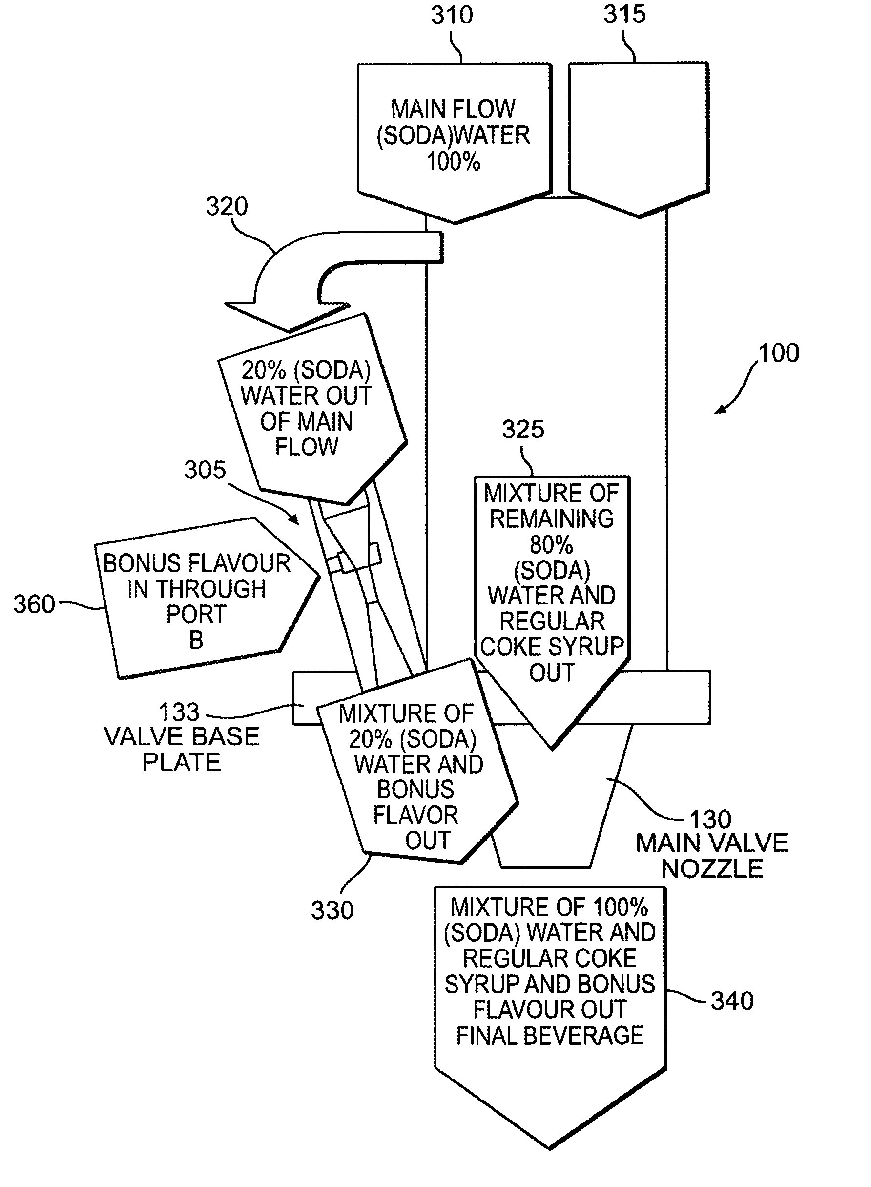
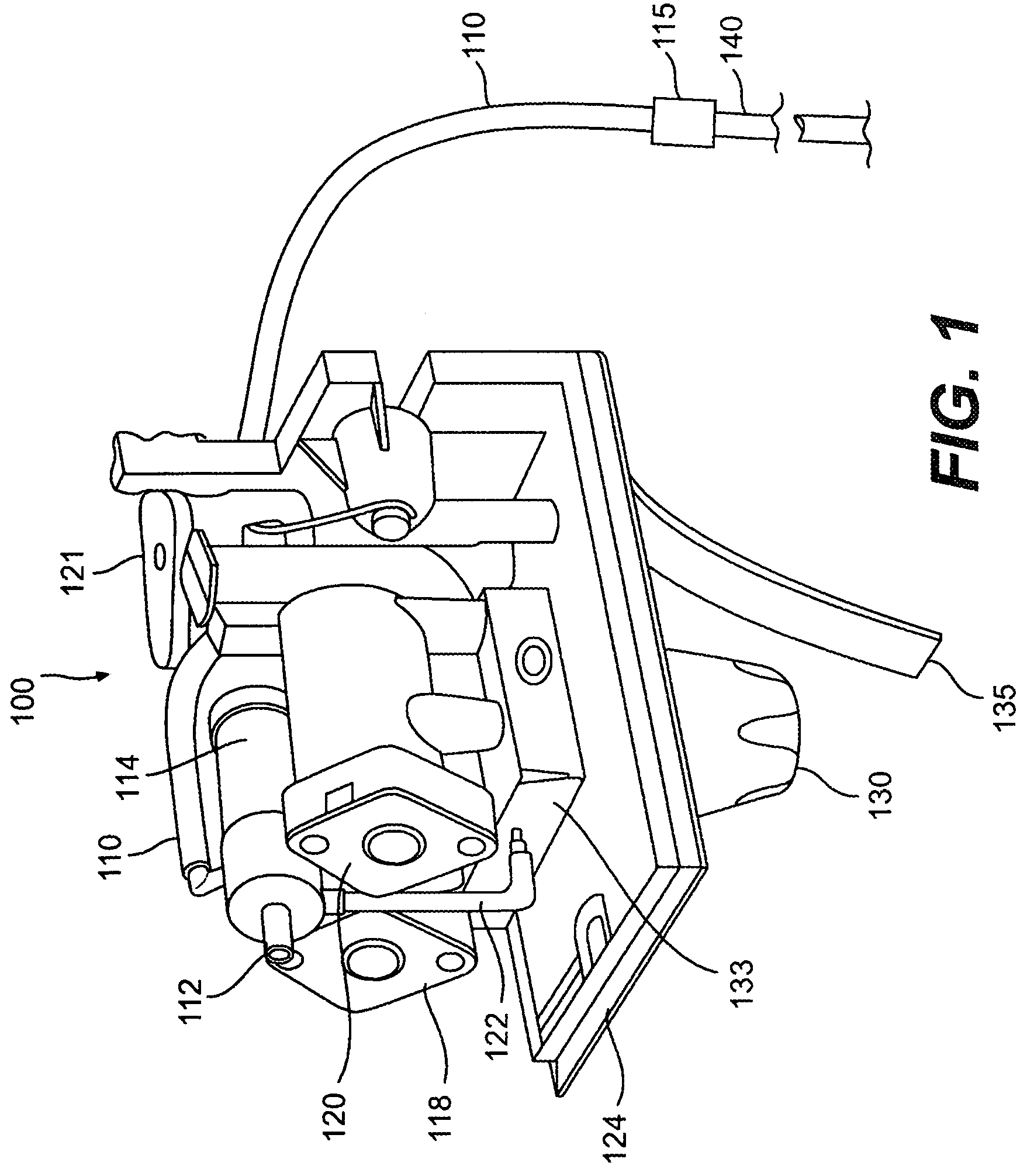
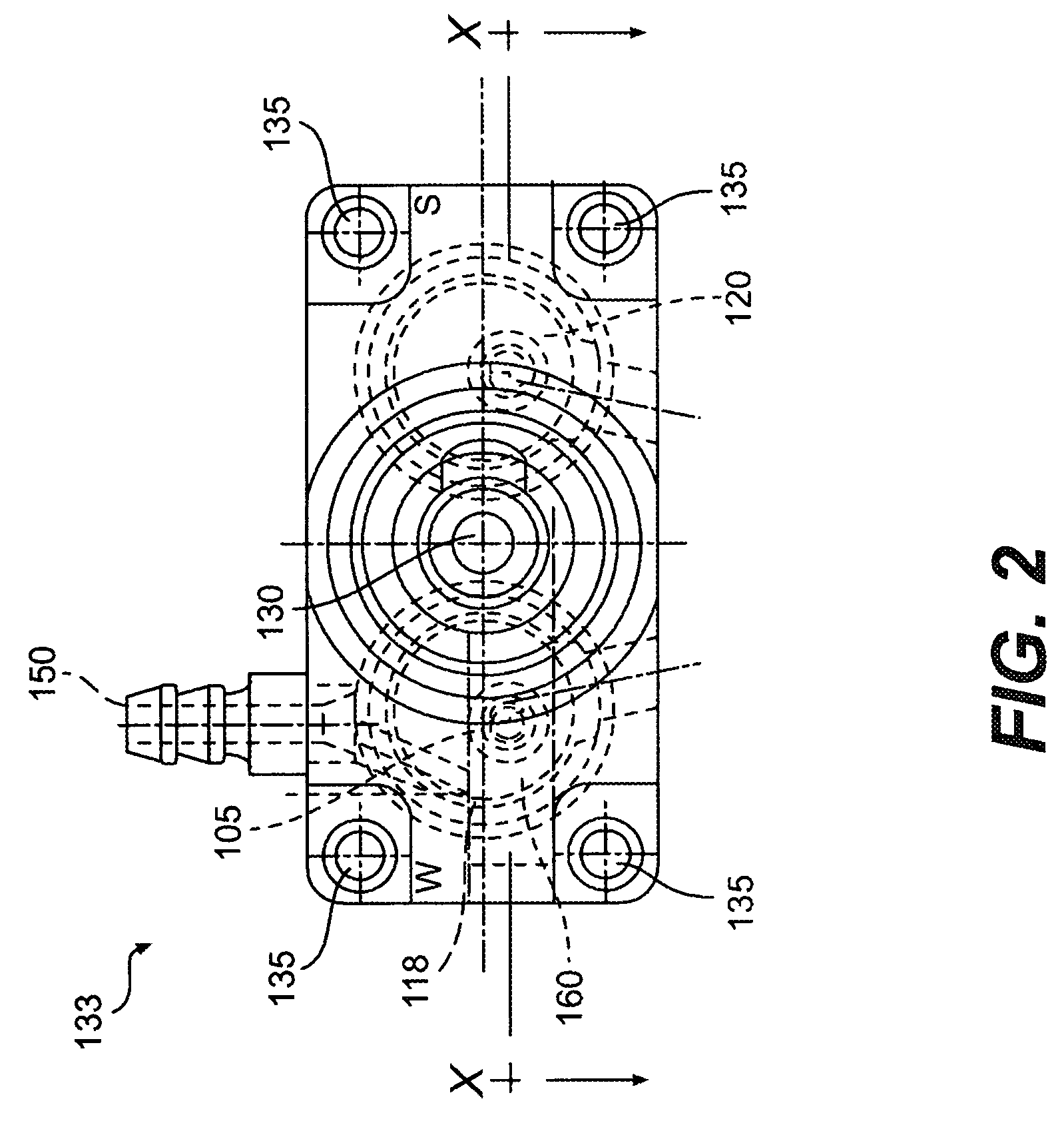
[0042]Referring now to FIG. 1, there is shown a liquid dispenser 100 having a dispense nozzle 130 mounted to the underside of a manifold 124. Also included is a valve base 133, which can be a mollified base, mounted to the top side of manifold 124 and which houses a Venturi valve 105 as shown in greater detail in FIG. 3 and discussed in further detail below. A tube 122 is connected at its lower end to an input port 150 and, at is upper end, to a needle control valve 112. Needle control valve 112 may be controlled by a flow control means 114. Needle control valve 112 may be a solenoid, a toggle valve or suitable control valve.

[0043]Dispenser 100 also includes syrup flow control 120 and water flow control 118 connected to valve base 133. Also included on manifold 124 is solenoid 121, which selectively opens and closes water flow control 118 and syrup flow control 120. Nozzle 130 can be a two-part nozzle. Water is directed through water flow control 118 through a top part of nozzle 130...


PUM

PropertyMeasurementUnit
diameteraaaaaaaaaa
diameter lengthsaaaaaaaaaa
angleaaaaaaaaaa

Abstract

A drink dispensing head incorporating a Venturi valve to utilize the motive force of a high pressure liquid to draw a low pressure liquid into the dispensing head without the need for a pumping means. A Venturi valve incorporated into a remote valve structure for adding a bonus flavor to a regular beverage dispenser without altering the existing valve structure.

Description

CROSS-REFERENCE TO RELATED APPLICATIONS[0001]This application is a non-provisional application of U.S. Provisional Application No. 60 / 533,243, entitled “LIQUID DISPENSING DEVICE”, filed on Dec. 31, 2003, and is a continuation-in-part of U.S. patent application Ser. No. 10 / 370,074, filed Feb. 21, 2003 entitled “LIQUID DISPENSING DEVICE”, the disclosures of which are hereby incorporated by reference in their entireties.BACKGROUND[0002]1. Field of the Invention[0003]The present invention relates generally to a soft drink dispensing machine. More specifically, the present invention relates to a soft drink dispensing machine device having a post mix dispensing head with an integrated bonus flavor Venturi valve. Even more specifically, the invention is directed to an external post mix dispensing head that utilizes motive energy from part of a water feed to entrain and mix a bonus flavor into a regular final beverage.[0004]2. Related Art[0005]Soft drink dispensing machines are well known. ...

Claims


Application Information

Patent Timeline
Patent Type & Authority Patents(United States)
IPC IPC(8): B67D5/56B67D7/74B01F3/08B67D1/00
CPCB01F3/0811B67D1/0051B67D1/0045B01F23/4105
Inventor ROEKENS, JURGENSHASKAYNE, PAULSHORT, GARY A.
Owner THE COCA-COLA CO
Why Eureka
Try Eureka